Warning: Trying to access array offset on null in /home/especiais/epsatisep/public_html/2015/EPS2015-wiki5/lib/plugins/caption/syntax/reference.php on line 68
Warning: Undefined array key "flabel1" in /home/especiais/epsatisep/public_html/2015/EPS2015-wiki5/lib/plugins/caption/syntax/reference.php on line 68
Warning: Undefined array key "flabel2" in /home/especiais/epsatisep/public_html/2015/EPS2015-wiki5/lib/plugins/caption/syntax/reference.php on line 68
Warning: Undefined array key "flabel3" in /home/especiais/epsatisep/public_html/2015/EPS2015-wiki5/lib/plugins/caption/syntax/reference.php on line 68
Warning: Undefined array key "tlabel4" in /home/especiais/epsatisep/public_html/2015/EPS2015-wiki5/lib/plugins/caption/syntax/reference.php on line 68
Warning: Undefined array key "tlabe2" in /home/especiais/epsatisep/public_html/2015/EPS2015-wiki5/lib/plugins/caption/syntax/reference.php on line 68
Warning: Undefined array key "tlabe10" in /home/especiais/epsatisep/public_html/2015/EPS2015-wiki5/lib/plugins/caption/syntax/reference.php on line 68
Warning: Undefined array key "flabel4" in /home/especiais/epsatisep/public_html/2015/EPS2015-wiki5/lib/plugins/caption/syntax/reference.php on line 68
Warning: Undefined array key "flabel5" in /home/especiais/epsatisep/public_html/2015/EPS2015-wiki5/lib/plugins/caption/syntax/reference.php on line 68
Warning: Undefined array key "flabel6" in /home/especiais/epsatisep/public_html/2015/EPS2015-wiki5/lib/plugins/caption/syntax/reference.php on line 68
Warning: Undefined array key "flabel6" in /home/especiais/epsatisep/public_html/2015/EPS2015-wiki5/lib/plugins/caption/syntax/reference.php on line 68
Warning: Undefined array key "flabel6" in /home/especiais/epsatisep/public_html/2015/EPS2015-wiki5/lib/plugins/caption/syntax/reference.php on line 68
Warning: Undefined array key "flabel7" in /home/especiais/epsatisep/public_html/2015/EPS2015-wiki5/lib/plugins/caption/syntax/reference.php on line 68
Warning: Undefined array key "flabel8" in /home/especiais/epsatisep/public_html/2015/EPS2015-wiki5/lib/plugins/caption/syntax/reference.php on line 68
Warning: Undefined array key "flabel9" in /home/especiais/epsatisep/public_html/2015/EPS2015-wiki5/lib/plugins/caption/syntax/reference.php on line 68
Warning: Undefined array key "flabel10" in /home/especiais/epsatisep/public_html/2015/EPS2015-wiki5/lib/plugins/caption/syntax/reference.php on line 68
Warning: Undefined array key "flabel11" in /home/especiais/epsatisep/public_html/2015/EPS2015-wiki5/lib/plugins/caption/syntax/reference.php on line 68
Warning: Undefined array key "flabel13" in /home/especiais/epsatisep/public_html/2015/EPS2015-wiki5/lib/plugins/caption/syntax/reference.php on line 68
Warning: Undefined array key "flabel14" in /home/especiais/epsatisep/public_html/2015/EPS2015-wiki5/lib/plugins/caption/syntax/reference.php on line 68
Warning: Undefined array key "flabel15" in /home/especiais/epsatisep/public_html/2015/EPS2015-wiki5/lib/plugins/caption/syntax/reference.php on line 68
Warning: Undefined array key "flabel16" in /home/especiais/epsatisep/public_html/2015/EPS2015-wiki5/lib/plugins/caption/syntax/reference.php on line 68
Warning: Undefined array key "flabel17" in /home/especiais/epsatisep/public_html/2015/EPS2015-wiki5/lib/plugins/caption/syntax/reference.php on line 68
Warning: Undefined array key "flabel18" in /home/especiais/epsatisep/public_html/2015/EPS2015-wiki5/lib/plugins/caption/syntax/reference.php on line 68
Warning: Undefined array key "flabel19" in /home/especiais/epsatisep/public_html/2015/EPS2015-wiki5/lib/plugins/caption/syntax/reference.php on line 68
Warning: Undefined array key "flabel20" in /home/especiais/epsatisep/public_html/2015/EPS2015-wiki5/lib/plugins/caption/syntax/reference.php on line 68
Warning: Undefined array key "flabel21" in /home/especiais/epsatisep/public_html/2015/EPS2015-wiki5/lib/plugins/caption/syntax/reference.php on line 68
Warning: Undefined array key "flabel22" in /home/especiais/epsatisep/public_html/2015/EPS2015-wiki5/lib/plugins/caption/syntax/reference.php on line 68
Warning: Undefined array key "flabel23" in /home/especiais/epsatisep/public_html/2015/EPS2015-wiki5/lib/plugins/caption/syntax/reference.php on line 68
Warning: Undefined array key "flabel23" in /home/especiais/epsatisep/public_html/2015/EPS2015-wiki5/lib/plugins/caption/syntax/reference.php on line 68
Warning: Undefined array key "flabel24" in /home/especiais/epsatisep/public_html/2015/EPS2015-wiki5/lib/plugins/caption/syntax/reference.php on line 68
Warning: Undefined array key "flabel25" in /home/especiais/epsatisep/public_html/2015/EPS2015-wiki5/lib/plugins/caption/syntax/reference.php on line 68
Warning: Undefined array key "flabel25" in /home/especiais/epsatisep/public_html/2015/EPS2015-wiki5/lib/plugins/caption/syntax/reference.php on line 68
Warning: Undefined array key "flabel26" in /home/especiais/epsatisep/public_html/2015/EPS2015-wiki5/lib/plugins/caption/syntax/reference.php on line 68
Warning: Undefined array key "flabel27" in /home/especiais/epsatisep/public_html/2015/EPS2015-wiki5/lib/plugins/caption/syntax/reference.php on line 68
Warning: Undefined array key "flabel28" in /home/especiais/epsatisep/public_html/2015/EPS2015-wiki5/lib/plugins/caption/syntax/reference.php on line 68
Warning: Undefined array key "flabel29" in /home/especiais/epsatisep/public_html/2015/EPS2015-wiki5/lib/plugins/caption/syntax/reference.php on line 68
Warning: Undefined array key "flabel30" in /home/especiais/epsatisep/public_html/2015/EPS2015-wiki5/lib/plugins/caption/syntax/reference.php on line 68
Warning: Undefined array key "flabel30" in /home/especiais/epsatisep/public_html/2015/EPS2015-wiki5/lib/plugins/caption/syntax/reference.php on line 68
Warning: Undefined array key "flabel30" in /home/especiais/epsatisep/public_html/2015/EPS2015-wiki5/lib/plugins/caption/syntax/reference.php on line 68
Warning: Undefined array key "flabel31" in /home/especiais/epsatisep/public_html/2015/EPS2015-wiki5/lib/plugins/caption/syntax/reference.php on line 68
Warning: Undefined array key "flabel32" in /home/especiais/epsatisep/public_html/2015/EPS2015-wiki5/lib/plugins/caption/syntax/reference.php on line 68
Warning: Undefined array key "flabel33" in /home/especiais/epsatisep/public_html/2015/EPS2015-wiki5/lib/plugins/caption/syntax/reference.php on line 68
Warning: Undefined array key "flabel34" in /home/especiais/epsatisep/public_html/2015/EPS2015-wiki5/lib/plugins/caption/syntax/reference.php on line 68
Warning: Undefined array key "flabel35" in /home/especiais/epsatisep/public_html/2015/EPS2015-wiki5/lib/plugins/caption/syntax/reference.php on line 68
Warning: Undefined array key "flabel35" in /home/especiais/epsatisep/public_html/2015/EPS2015-wiki5/lib/plugins/caption/syntax/reference.php on line 68
Warning: Undefined array key "tlabel1" in /home/especiais/epsatisep/public_html/2015/EPS2015-wiki5/lib/plugins/caption/syntax/reference.php on line 68
Warning: Undefined array key "tlabel2" in /home/especiais/epsatisep/public_html/2015/EPS2015-wiki5/lib/plugins/caption/syntax/reference.php on line 68
Warning: Undefined array key "tlabel3" in /home/especiais/epsatisep/public_html/2015/EPS2015-wiki5/lib/plugins/caption/syntax/reference.php on line 68
Warning: Undefined array key "flabel38" in /home/especiais/epsatisep/public_html/2015/EPS2015-wiki5/lib/plugins/caption/syntax/reference.php on line 68
Warning: Undefined array key "flabel39" in /home/especiais/epsatisep/public_html/2015/EPS2015-wiki5/lib/plugins/caption/syntax/reference.php on line 68
Warning: Undefined array key "flabel40" in /home/especiais/epsatisep/public_html/2015/EPS2015-wiki5/lib/plugins/caption/syntax/reference.php on line 68
Warning: Undefined array key "flabel41" in /home/especiais/epsatisep/public_html/2015/EPS2015-wiki5/lib/plugins/caption/syntax/reference.php on line 68
Warning: Undefined array key "flabel42" in /home/especiais/epsatisep/public_html/2015/EPS2015-wiki5/lib/plugins/caption/syntax/reference.php on line 68
Warning: Undefined array key "flabel43" in /home/especiais/epsatisep/public_html/2015/EPS2015-wiki5/lib/plugins/caption/syntax/reference.php on line 68
Warning: Undefined array key "flabel44" in /home/especiais/epsatisep/public_html/2015/EPS2015-wiki5/lib/plugins/caption/syntax/reference.php on line 68
Warning: Undefined array key "flabel45" in /home/especiais/epsatisep/public_html/2015/EPS2015-wiki5/lib/plugins/caption/syntax/reference.php on line 68
Warning: Undefined array key "flabel46" in /home/especiais/epsatisep/public_html/2015/EPS2015-wiki5/lib/plugins/caption/syntax/reference.php on line 68
Warning: Undefined array key "flabel47" in /home/especiais/epsatisep/public_html/2015/EPS2015-wiki5/lib/plugins/caption/syntax/reference.php on line 68
Warning: Undefined array key "flabel48" in /home/especiais/epsatisep/public_html/2015/EPS2015-wiki5/lib/plugins/caption/syntax/reference.php on line 68
Warning: Undefined array key "flabel49" in /home/especiais/epsatisep/public_html/2015/EPS2015-wiki5/lib/plugins/caption/syntax/reference.php on line 68
Warning: Undefined array key "flabe50" in /home/especiais/epsatisep/public_html/2015/EPS2015-wiki5/lib/plugins/caption/syntax/reference.php on line 68
Warning: Undefined array key "flabe51" in /home/especiais/epsatisep/public_html/2015/EPS2015-wiki5/lib/plugins/caption/syntax/reference.php on line 68
Warning: Undefined array key "flabel52" in /home/especiais/epsatisep/public_html/2015/EPS2015-wiki5/lib/plugins/caption/syntax/reference.php on line 68
Warning: Undefined array key "flabel53" in /home/especiais/epsatisep/public_html/2015/EPS2015-wiki5/lib/plugins/caption/syntax/reference.php on line 68
Warning: Undefined array key "flabel54" in /home/especiais/epsatisep/public_html/2015/EPS2015-wiki5/lib/plugins/caption/syntax/reference.php on line 68
Warning: Undefined array key "flabe55" in /home/especiais/epsatisep/public_html/2015/EPS2015-wiki5/lib/plugins/caption/syntax/reference.php on line 68
Warning: Undefined array key "flabel56" in /home/especiais/epsatisep/public_html/2015/EPS2015-wiki5/lib/plugins/caption/syntax/reference.php on line 68
Warning: Undefined array key "flabel57" in /home/especiais/epsatisep/public_html/2015/EPS2015-wiki5/lib/plugins/caption/syntax/reference.php on line 68
Warning: Undefined array key "flabe58" in /home/especiais/epsatisep/public_html/2015/EPS2015-wiki5/lib/plugins/caption/syntax/reference.php on line 68
Warning: Undefined array key "flabel59" in /home/especiais/epsatisep/public_html/2015/EPS2015-wiki5/lib/plugins/caption/syntax/reference.php on line 68
Warning: Undefined array key "flabel60" in /home/especiais/epsatisep/public_html/2015/EPS2015-wiki5/lib/plugins/caption/syntax/reference.php on line 68
Warning: Undefined array key "flabel61" in /home/especiais/epsatisep/public_html/2015/EPS2015-wiki5/lib/plugins/caption/syntax/reference.php on line 68
Warning: Undefined array key "flabel62" in /home/especiais/epsatisep/public_html/2015/EPS2015-wiki5/lib/plugins/caption/syntax/reference.php on line 68
Warning: Undefined array key "flabel63" in /home/especiais/epsatisep/public_html/2015/EPS2015-wiki5/lib/plugins/caption/syntax/reference.php on line 68
Warning: Undefined array key "flabel64" in /home/especiais/epsatisep/public_html/2015/EPS2015-wiki5/lib/plugins/caption/syntax/reference.php on line 68
Warning: Undefined array key "flabel65" in /home/especiais/epsatisep/public_html/2015/EPS2015-wiki5/lib/plugins/caption/syntax/reference.php on line 68
Warning: Undefined array key "flabel66" in /home/especiais/epsatisep/public_html/2015/EPS2015-wiki5/lib/plugins/caption/syntax/reference.php on line 68
Warning: Undefined array key "flabel67" in /home/especiais/epsatisep/public_html/2015/EPS2015-wiki5/lib/plugins/caption/syntax/reference.php on line 68
Warning: Undefined array key "flabel68" in /home/especiais/epsatisep/public_html/2015/EPS2015-wiki5/lib/plugins/caption/syntax/reference.php on line 68
Warning: Undefined array key "flabel69" in /home/especiais/epsatisep/public_html/2015/EPS2015-wiki5/lib/plugins/caption/syntax/reference.php on line 68
Warning: Undefined array key "flabel70" in /home/especiais/epsatisep/public_html/2015/EPS2015-wiki5/lib/plugins/caption/syntax/reference.php on line 68
Warning: Undefined array key "flabel71" in /home/especiais/epsatisep/public_html/2015/EPS2015-wiki5/lib/plugins/caption/syntax/reference.php on line 68
Warning: Undefined array key "flabel72" in /home/especiais/epsatisep/public_html/2015/EPS2015-wiki5/lib/plugins/caption/syntax/reference.php on line 68
Warning: Undefined array key "flabel73" in /home/especiais/epsatisep/public_html/2015/EPS2015-wiki5/lib/plugins/caption/syntax/reference.php on line 68
Warning: Undefined array key "flabel74" in /home/especiais/epsatisep/public_html/2015/EPS2015-wiki5/lib/plugins/caption/syntax/reference.php on line 68
Warning: Undefined array key "flabel75" in /home/especiais/epsatisep/public_html/2015/EPS2015-wiki5/lib/plugins/caption/syntax/reference.php on line 68
Warning: Undefined array key "flabel76" in /home/especiais/epsatisep/public_html/2015/EPS2015-wiki5/lib/plugins/caption/syntax/reference.php on line 68
Warning: Undefined array key "flabel77" in /home/especiais/epsatisep/public_html/2015/EPS2015-wiki5/lib/plugins/caption/syntax/reference.php on line 68
Warning: Undefined array key "flabel78" in /home/especiais/epsatisep/public_html/2015/EPS2015-wiki5/lib/plugins/caption/syntax/reference.php on line 68
Warning: Undefined array key "flabel79" in /home/especiais/epsatisep/public_html/2015/EPS2015-wiki5/lib/plugins/caption/syntax/reference.php on line 68
Warning: Undefined array key "flabel80" in /home/especiais/epsatisep/public_html/2015/EPS2015-wiki5/lib/plugins/caption/syntax/reference.php on line 68
Warning: Undefined array key "flabel81" in /home/especiais/epsatisep/public_html/2015/EPS2015-wiki5/lib/plugins/caption/syntax/reference.php on line 68
Warning: Undefined array key "flabel82" in /home/especiais/epsatisep/public_html/2015/EPS2015-wiki5/lib/plugins/caption/syntax/reference.php on line 68
Warning: Undefined array key "flabel83" in /home/especiais/epsatisep/public_html/2015/EPS2015-wiki5/lib/plugins/caption/syntax/reference.php on line 68
Warning: Undefined array key "flabel84" in /home/especiais/epsatisep/public_html/2015/EPS2015-wiki5/lib/plugins/caption/syntax/reference.php on line 68
Warning: Undefined array key "flabel84" in /home/especiais/epsatisep/public_html/2015/EPS2015-wiki5/lib/plugins/caption/syntax/reference.php on line 68
Warning: Undefined array key "flabel85" in /home/especiais/epsatisep/public_html/2015/EPS2015-wiki5/lib/plugins/caption/syntax/reference.php on line 68
Warning: Undefined array key "flabel86" in /home/especiais/epsatisep/public_html/2015/EPS2015-wiki5/lib/plugins/caption/syntax/reference.php on line 68
Warning: Undefined array key "flabel86" in /home/especiais/epsatisep/public_html/2015/EPS2015-wiki5/lib/plugins/caption/syntax/reference.php on line 68
Warning: Undefined array key "flabel87" in /home/especiais/epsatisep/public_html/2015/EPS2015-wiki5/lib/plugins/caption/syntax/reference.php on line 68
Warning: Undefined array key "flabel88" in /home/especiais/epsatisep/public_html/2015/EPS2015-wiki5/lib/plugins/caption/syntax/reference.php on line 68
Warning: Undefined array key "flabel89" in /home/especiais/epsatisep/public_html/2015/EPS2015-wiki5/lib/plugins/caption/syntax/reference.php on line 68
Warning: Undefined array key "flabel90" in /home/especiais/epsatisep/public_html/2015/EPS2015-wiki5/lib/plugins/caption/syntax/reference.php on line 68
Warning: Undefined array key "flabel91" in /home/especiais/epsatisep/public_html/2015/EPS2015-wiki5/lib/plugins/caption/syntax/reference.php on line 68
Warning: Undefined array key "flabel92" in /home/especiais/epsatisep/public_html/2015/EPS2015-wiki5/lib/plugins/caption/syntax/reference.php on line 68
Warning: Undefined array key "flabel93" in /home/especiais/epsatisep/public_html/2015/EPS2015-wiki5/lib/plugins/caption/syntax/reference.php on line 68
Warning: Undefined array key "flabel94" in /home/especiais/epsatisep/public_html/2015/EPS2015-wiki5/lib/plugins/caption/syntax/reference.php on line 68
Warning: Undefined array key "flabel95" in /home/especiais/epsatisep/public_html/2015/EPS2015-wiki5/lib/plugins/caption/syntax/reference.php on line 68
Warning: Undefined array key "flabel95" in /home/especiais/epsatisep/public_html/2015/EPS2015-wiki5/lib/plugins/caption/syntax/reference.php on line 68
Warning: Undefined array key "flabel96" in /home/especiais/epsatisep/public_html/2015/EPS2015-wiki5/lib/plugins/caption/syntax/reference.php on line 68
Warning: Undefined array key "flabel97" in /home/especiais/epsatisep/public_html/2015/EPS2015-wiki5/lib/plugins/caption/syntax/reference.php on line 68
Warning: Undefined array key "flabel98" in /home/especiais/epsatisep/public_html/2015/EPS2015-wiki5/lib/plugins/caption/syntax/reference.php on line 68
Warning: Undefined array key "flabel99" in /home/especiais/epsatisep/public_html/2015/EPS2015-wiki5/lib/plugins/caption/syntax/reference.php on line 68
Warning: Undefined array key "flabel100" in /home/especiais/epsatisep/public_html/2015/EPS2015-wiki5/lib/plugins/caption/syntax/reference.php on line 68
Warning: Undefined array key "flabel100" in /home/especiais/epsatisep/public_html/2015/EPS2015-wiki5/lib/plugins/caption/syntax/reference.php on line 68
Warning: Undefined array key "flabel101" in /home/especiais/epsatisep/public_html/2015/EPS2015-wiki5/lib/plugins/caption/syntax/reference.php on line 68
Warning: Undefined array key "flabel102" in /home/especiais/epsatisep/public_html/2015/EPS2015-wiki5/lib/plugins/caption/syntax/reference.php on line 68
Warning: Undefined array key "flabel103" in /home/especiais/epsatisep/public_html/2015/EPS2015-wiki5/lib/plugins/caption/syntax/reference.php on line 68
Warning: Undefined array key "flabel104" in /home/especiais/epsatisep/public_html/2015/EPS2015-wiki5/lib/plugins/caption/syntax/reference.php on line 68
Warning: Undefined array key "flabel105" in /home/especiais/epsatisep/public_html/2015/EPS2015-wiki5/lib/plugins/caption/syntax/reference.php on line 68
Warning: Undefined array key "flabel106" in /home/especiais/epsatisep/public_html/2015/EPS2015-wiki5/lib/plugins/caption/syntax/reference.php on line 68
Warning: Undefined array key "flabel107" in /home/especiais/epsatisep/public_html/2015/EPS2015-wiki5/lib/plugins/caption/syntax/reference.php on line 68
Warning: Undefined array key "flabel108" in /home/especiais/epsatisep/public_html/2015/EPS2015-wiki5/lib/plugins/caption/syntax/reference.php on line 68
Warning: Undefined array key "flabel109" in /home/especiais/epsatisep/public_html/2015/EPS2015-wiki5/lib/plugins/caption/syntax/reference.php on line 68
Warning: Undefined array key "flabel110" in /home/especiais/epsatisep/public_html/2015/EPS2015-wiki5/lib/plugins/caption/syntax/reference.php on line 68
Warning: Undefined array key "flabel111" in /home/especiais/epsatisep/public_html/2015/EPS2015-wiki5/lib/plugins/caption/syntax/reference.php on line 68
Warning: Undefined array key "flabel112" in /home/especiais/epsatisep/public_html/2015/EPS2015-wiki5/lib/plugins/caption/syntax/reference.php on line 68
Warning: Undefined array key "flabel113" in /home/especiais/epsatisep/public_html/2015/EPS2015-wiki5/lib/plugins/caption/syntax/reference.php on line 68
Warning: Undefined array key "flabel114" in /home/especiais/epsatisep/public_html/2015/EPS2015-wiki5/lib/plugins/caption/syntax/reference.php on line 68
Warning: Undefined array key "flabel115" in /home/especiais/epsatisep/public_html/2015/EPS2015-wiki5/lib/plugins/caption/syntax/reference.php on line 68
Warning: Undefined array key "flabel116" in /home/especiais/epsatisep/public_html/2015/EPS2015-wiki5/lib/plugins/caption/syntax/reference.php on line 68
Warning: Undefined array key "flabel117" in /home/especiais/epsatisep/public_html/2015/EPS2015-wiki5/lib/plugins/caption/syntax/reference.php on line 68
Warning: Undefined array key "flabel118" in /home/especiais/epsatisep/public_html/2015/EPS2015-wiki5/lib/plugins/caption/syntax/reference.php on line 68
Warning: Undefined array key "flabel119" in /home/especiais/epsatisep/public_html/2015/EPS2015-wiki5/lib/plugins/caption/syntax/reference.php on line 68
Warning: Undefined array key "flabel120" in /home/especiais/epsatisep/public_html/2015/EPS2015-wiki5/lib/plugins/caption/syntax/reference.php on line 68
Warning: Undefined array key "tlabel14" in /home/especiais/epsatisep/public_html/2015/EPS2015-wiki5/lib/plugins/caption/syntax/reference.php on line 68
Warning: Undefined array key "flabel122" in /home/especiais/epsatisep/public_html/2015/EPS2015-wiki5/lib/plugins/caption/syntax/reference.php on line 68
Warning: Undefined array key "flabel123" in /home/especiais/epsatisep/public_html/2015/EPS2015-wiki5/lib/plugins/caption/syntax/reference.php on line 68
Warning: Undefined array key "flabel124" in /home/especiais/epsatisep/public_html/2015/EPS2015-wiki5/lib/plugins/caption/syntax/reference.php on line 68
Warning: Undefined array key "flabel125" in /home/especiais/epsatisep/public_html/2015/EPS2015-wiki5/lib/plugins/caption/syntax/reference.php on line 68
Warning: Undefined array key "flabel126" in /home/especiais/epsatisep/public_html/2015/EPS2015-wiki5/lib/plugins/caption/syntax/reference.php on line 68
Warning: Undefined array key "flabel127" in /home/especiais/epsatisep/public_html/2015/EPS2015-wiki5/lib/plugins/caption/syntax/reference.php on line 68
Warning: Undefined array key "flabel128" in /home/especiais/epsatisep/public_html/2015/EPS2015-wiki5/lib/plugins/caption/syntax/reference.php on line 68
Warning: Undefined array key "flabel129" in /home/especiais/epsatisep/public_html/2015/EPS2015-wiki5/lib/plugins/caption/syntax/reference.php on line 68
Warning: Undefined array key "flabel130" in /home/especiais/epsatisep/public_html/2015/EPS2015-wiki5/lib/plugins/caption/syntax/reference.php on line 68
Warning: Undefined array key "flabel131" in /home/especiais/epsatisep/public_html/2015/EPS2015-wiki5/lib/plugins/caption/syntax/reference.php on line 68
Warning: Undefined array key "flabel132" in /home/especiais/epsatisep/public_html/2015/EPS2015-wiki5/lib/plugins/caption/syntax/reference.php on line 68
Warning: Undefined array key "flabel133" in /home/especiais/epsatisep/public_html/2015/EPS2015-wiki5/lib/plugins/caption/syntax/reference.php on line 68
Warning: Undefined array key "flabel134" in /home/especiais/epsatisep/public_html/2015/EPS2015-wiki5/lib/plugins/caption/syntax/reference.php on line 68
Warning: Undefined array key "flabel135" in /home/especiais/epsatisep/public_html/2015/EPS2015-wiki5/lib/plugins/caption/syntax/reference.php on line 68
Warning: Undefined array key "flabel135" in /home/especiais/epsatisep/public_html/2015/EPS2015-wiki5/lib/plugins/caption/syntax/reference.php on line 68
Warning: Undefined array key "flabel136" in /home/especiais/epsatisep/public_html/2015/EPS2015-wiki5/lib/plugins/caption/syntax/reference.php on line 68
Warning: Undefined array key "flabel136" in /home/especiais/epsatisep/public_html/2015/EPS2015-wiki5/lib/plugins/caption/syntax/reference.php on line 68
Warning: Undefined array key "flabel137" in /home/especiais/epsatisep/public_html/2015/EPS2015-wiki5/lib/plugins/caption/syntax/reference.php on line 68
Warning: Undefined array key "flabel138" in /home/especiais/epsatisep/public_html/2015/EPS2015-wiki5/lib/plugins/caption/syntax/reference.php on line 68
Warning: Undefined array key "flabel138" in /home/especiais/epsatisep/public_html/2015/EPS2015-wiki5/lib/plugins/caption/syntax/reference.php on line 68
Warning: Undefined array key "flabel139" in /home/especiais/epsatisep/public_html/2015/EPS2015-wiki5/lib/plugins/caption/syntax/reference.php on line 68
Warning: Undefined array key "flabel140" in /home/especiais/epsatisep/public_html/2015/EPS2015-wiki5/lib/plugins/caption/syntax/reference.php on line 68
Warning: Undefined array key "flabel141" in /home/especiais/epsatisep/public_html/2015/EPS2015-wiki5/lib/plugins/caption/syntax/reference.php on line 68
Warning: Undefined array key "flabel142" in /home/especiais/epsatisep/public_html/2015/EPS2015-wiki5/lib/plugins/caption/syntax/reference.php on line 68
Warning: Undefined array key "flabel143" in /home/especiais/epsatisep/public_html/2015/EPS2015-wiki5/lib/plugins/caption/syntax/reference.php on line 68
Warning: Undefined array key "flabel143" in /home/especiais/epsatisep/public_html/2015/EPS2015-wiki5/lib/plugins/caption/syntax/reference.php on line 68
Warning: Undefined array key "flabel144" in /home/especiais/epsatisep/public_html/2015/EPS2015-wiki5/lib/plugins/caption/syntax/reference.php on line 68
Warning: Undefined array key "flabel145" in /home/especiais/epsatisep/public_html/2015/EPS2015-wiki5/lib/plugins/caption/syntax/reference.php on line 68
Warning: Undefined array key "flabel146" in /home/especiais/epsatisep/public_html/2015/EPS2015-wiki5/lib/plugins/caption/syntax/reference.php on line 68
Warning: Undefined array key "flabel147" in /home/especiais/epsatisep/public_html/2015/EPS2015-wiki5/lib/plugins/caption/syntax/reference.php on line 68
Warning: Undefined array key "flabel148" in /home/especiais/epsatisep/public_html/2015/EPS2015-wiki5/lib/plugins/caption/syntax/reference.php on line 68
Warning: Undefined array key "flabel149" in /home/especiais/epsatisep/public_html/2015/EPS2015-wiki5/lib/plugins/caption/syntax/reference.php on line 68
Warning: Undefined array key "flabel150" in /home/especiais/epsatisep/public_html/2015/EPS2015-wiki5/lib/plugins/caption/syntax/reference.php on line 68
Warning: Undefined array key "flabel151" in /home/especiais/epsatisep/public_html/2015/EPS2015-wiki5/lib/plugins/caption/syntax/reference.php on line 68
Warning: Undefined array key "flabel152" in /home/especiais/epsatisep/public_html/2015/EPS2015-wiki5/lib/plugins/caption/syntax/reference.php on line 68
Warning: Undefined array key "flabel153" in /home/especiais/epsatisep/public_html/2015/EPS2015-wiki5/lib/plugins/caption/syntax/reference.php on line 68
Warning: Undefined array key "flabel154" in /home/especiais/epsatisep/public_html/2015/EPS2015-wiki5/lib/plugins/caption/syntax/reference.php on line 68
Warning: Undefined array key "flabel154" in /home/especiais/epsatisep/public_html/2015/EPS2015-wiki5/lib/plugins/caption/syntax/reference.php on line 68
Table of Contents
Report
Title : Autonomous Sailing Boat
Author(s):
- Roberto Giordano
- Gary Jonathan Rabone
- Marc Navarrete Hill
- Imre Asztalos
- Thies Gunther
Acknowledgement
Finishing the 4 months project of the autonomous sail boat, we want to thank all the teachers involved in the different classes taught, as well as the supervisors that guided us patiently and competent through the whole project. It was for all of us a great experience full of hard work, great companionship that extended at the end our horizons in on a cultural and also educational level. Furthermore we are thankful that the “Instituto Superior de Engenharia do Porto” (ISEP) offered us the chance to stay in Porto and do the European Project Semester (EPS). A special thanks to Fernando Ferreira who was a great support throughout the whole project. He guided us towards the accomplishment of the project and ensured the correct progress.
Abstract
At present, the ocean suffers greatly as a result of ever-growing population and disasters occur all over the world. A manoeuvrable ocean exploring monitoring system has been a state of the art subject for several years. The advancements in the field can be used in several market sectors and developed overtime. This system can be used for research and development purposes. The system can monitor oceans while maintaining the desired energy efficiency measures. Horizon Sail is developing an innovative rigid-wing for a sailboat likely to sail the oceans and capture data without human interaction. The product will be marketed on several platforms to be used widely in several industries. Many technical aspects still have to be studied and developed, especially regarding the boat that will be subjected to adverse climate conditions in unmanned areas and reducing the human assistance if damage occurs.
Abbreviations
| Abbreviation | Description |
|---|---|
| 4P | Product, Place, Price and Promotion |
| ${a_1}$ | Distance from Hull and Top of the Mast |
| ${a_2}$ | High of the Geometrical Centre of the Reefed Sail |
| Ah | Ampere hour |
| AIDA | Attention, Interest, Desire and Action |
| AIS | Automatic Identification System |
| AMS | Autonomous Marine System |
| AP | Aft Perpendicular |
| ${A_x}$ | Maximum Section Area Below Designed Waterline |
| B | Beam |
| ${B_1}$ | New Buoyancy Centre |
| B2B | Business to Business |
| B2G | Business to Government |
| BD | Boom Height Above Deck |
| ${B_{WL}}$ | Beam of Waterline |
| CANbus | Control Area Network |
| ${C_B}$ | Block Coefficient |
| CB | Centre of Buoyancy |
| CCS | Carbon Capture and Storage |
| ${C_D}$ | Drag Coefficient |
| CE | Aerodynamic Centre of Effort |
| ${C_F}$ | Skin Friction Coefficient |
| CG | Centre of Gravity |
| CHP | Combined Heat and Power |
| ${C_L}$ | Lift Coefficient |
| CLR | Hydrodynamic Centre of Lateral Resistance |
| ${C_{Lr}}$ | Rudder Lift Coefficient |
| CNC | Computer Numerical Control |
| ${CO_2}$ | Carbon Dioxide |
| CP | Prismatic Coefficient |
| CS | Carbon Capturing System |
| d | Distance |
| D | Drag |
| dBm | Decibel-Milliwatts |
| DFA | Design for Assembly |
| DFD | Design for Disassembly |
| ${D_{WL}}$ | Designed Waterline |
| EEPROM | Electrically Erasable Programmable Read-Only Memory |
| EMAS | European Management and Audit Scheme |
| EPS | European Project Semester |
| EU | European Union |
| ${F_1}$ | Hydrodynamic Force |
| ${F_A}$ | Aerodynamic Force |
| ${F_h}$ | Horizontal Boom Force |
| ${F_{LAT}}$ | Aerodynamic Side Force |
| ${F_M}$ | Driving Force |
| FoS | Factor of Safety |
| FP | Forward Perpendicular |
| ft | Feet |
| ${F_V}$ | Vertical Boom Force |
| G | Centre of gravity |
| GDP | Gross Domestic Produce |
| GPIO | General Purpose Input/output |
| GPRS | General Packet Radio Service |
| GPS | Global Positioning System |
| GSM | Corporate Telephone Preference Service |
| GUI | Graphical User Interface |
| GWh | Giga Watt hour |
| h | Height |
| HMI | Human Machine Interface |
| ISEP | Instituto Superior de Engenharia do Porto |
| ISO | International Organisation for Standardisation |
| i/o | input/output |
| kg | kilogram |
| l | Horizontal Length of Rudder at Centre of Effort, or Long Span of Panel, or Stiffener Length |
| L | Lift |
| LCB | Longitudinal Centre of Buoyancy |
| ${L_{OA}}$ | Length overall |
| LOBO | Land/Ocean Biogeochemical Observatory |
| ${L_{PP}}$ | Length Between Perpendiculars |
| LSA | Autonomous System Laboratory |
| ${L_{WL}}$ | Length of waterline |
| M | Bending moment, or metacentre |
| m | Meter |
| ${M_1}$, / ${M_2}$ | Motor 1/2 |
| MHz | Megahertz |
| MIS | Management Information System |
| ${M_r}$ | Rudder Bending Moment |
| MW | Mega Watt |
| N | Newton |
| NACA (NASA) | National Advisory Committee for Aeronautics |
| NERC | National Environment Resource Council |
| NIST | National Institute of Standards and Technology |
| NOC | National Oceanography Centre |
| ɵ | Heel angle |
| P | Height of Mainsail (IOR), or Propeller Pitch, or Load, General |
| ${P_a}$ | Dimensioning Aft Stay Load |
| ${P_{fo}}$ | Dimensioning Outer Forestay Load |
| Pi | Rasperry Pi |
| ${P_{LAT}}$ | Hydrodynamic Side Force |
| PSC | Programmable Servo Controller |
| PWM | Pulse Width Modulation |
| R&D | Research and Development |
| RADAR | Radio Detection and Range |
| ${R_F}$ | Frictional Resistance |
| RM | Righting Moment |
| ${R_n}$ | Reynolds Number |
| ROHS | Restriction of Hazardous Substances |
| SD | Secure Digital |
| SDK | Software Development Kit |
| SRAM | Static Random-Access Memory |
| S.W.O.T | Strengths, Weaknesses, Opportunities and Threats |
| SAN | Styrene Acryrin |
| SI | International System of Units |
| ${S_W}$ | Wetted Surface Area |
| T | Draft |
| ${T_1}$ | Wave Period, or Transverse Foresail Force |
| ${T_2}$ | Transverse Mainsail Force |
| ${T_{boom}}$ | Transverse Force at Foot of Mainsail |
| ${T_{bu}}$ | Upper Boom Force |
| ${t_c}$ | Core Thickness |
| ${T_{head}}$ | Transverse Force at Top of Mainsail |
| ${T_{hl}}$ | Lower Shroud Force |
| ${T_{hu}}$ | Upper Shroud Force |
| TWh | Tera Watt Hour |
| UART | Universal Asynchronous Receiver/Transmitter |
| US | United States |
| USB | Universal Serial Bus |
| V | Volt |
| ${V_A}$ | Apparent Wind Directions |
| ${V_d}$ | Volume Displacement |
| VOC | Volatile Organic Compounds |
| ${V_S}$ | Yacht Speed (m/s) |
| Wh | Watt Hour |
| WIPE | World Intellectual Property Organisation |
| XML | Extensible Markup Language |
| WOW | Wally Over Wing |
| X, Y, Z | Cartesian Coordinates, Origin at FP, X Afterwards, Y to Starboard, Z Vertically Upwards |
| α | Angle of Attack |
| λ | Wavelength or Taper Ratio |
| ρ | Density |
1. Introduction
“Talent wins games, but teamwork and intelligence win championships.” - Michael Jordan
1.1 Presentation
Our team consists of five multinational, interdisciplinary student members who have undertaken the European Project Semester programme 2015 at the Instituto Superior de Engenharia do Porto otherwise known as ISEP. The programme commenced on the 23/02/2015 and it will last four months, finalising on the 26/02/2015. The semester is based on a group project, “Autonomous Sailing Boat”.
The programme also offers additional classes such as Team building, Project Management, Communication, Marketing, Sustainability and Ethics & Deontology all of which are designed to aid the project completion.
Our Crew
Table 1 displays our crew.
| Roberto Giordano | Gary Jonathan Rabone | Marc Navarrete Hill | Imre Asztalos | Thies Günther |
|---|---|---|---|---|
 |  |  |  |  |
| Management in Engineering | Mechanical Systems Engineering | Industrial Design & Product Development | Electrical Engineering | Sales & Purchase in Engineering |
| Italy | Scotland | Catalonia | Hungary | Germany |
Figure 1 displays our first idea of a sailboat.

1.2 Motivation
The decision to select a suitable project which covered all our skill sets was a difficult one out of the 15 project proposals. The final choice was to design, manufacture and deliver an autonomous sailboat to a client who specialises in the field of autonomous systems. The motivation for our team decision is based on several conditions, listed below:
- Team Contribution: It takes a lot to make people a winning team. Everybody's contribution is important and this is vital in achieving our combined goal.
- Innovation: For good ideas and true innovation, you need human interactions, conflict, argument and debates. This is something we all possess as a team and through thick and thin we will achieve new heights with this project.
- Challenge: Overcoming a problem takes time and effort but more importantly team support. The cooperation each member plays in our team will contribute to our overall success and each individual will be supported throughout to overcome any challenges faced.
Each team member also had their say:
- Roberto Giordano: “I selected this project to better understand an ancient but still modern mode of transportation, traditional and common but also exciting. With this project I can improve my practical skills and work on something tangible and that can be useful for everyday life.”
- Gary Jonathan Rabone: “I chose the project due to its challenge and relevance to my field of study, furthermore its appeal was grown by working with an accomplished institute in the autonomous control system sector.”
- Marc Navarrete Hill: “I selected that project because I immediately recognised that I could implement all the design skills that I have currently studied during my advanced education and moreover because the sea is one of my passions and always wanted to design a naval mode of transport.”
- Imre Asztalos: “Every summer I go sailing so this project was very attractive since it is one of my favourite hobbies. I'm looking forward to using my sailing and electronic knowledge in this project. I think this project is not easy, but it will be a very good experience for all of us in the team.”
- Thies Gunther: “The project was appealing I had the feeling that in our interdisciplinary team everybody could contribute to the project. Due to the fact the technology of the autonomous sailing is relatively new, we all can benefit from the knowledge of new technology.”
1.3 Problem
Although none of our members is specialised in naval engineering, we felt that there is a strong market need for autonomous sailing boats. There is a high interest in doing research missions in all different water environments and doing this autonomously would enhance our possibility in the market. Therefore we have to first think about the actual mission that the boat has to fulfil. Based on this we need to define the dimensions of the boat and select the best and cost efficient material. Meanwhile we have to research the best possibilities to design the hull and start off with calculations as well as simulations to ensure safety and stability of the boat in its diverse environments. Doing so, we will take into account the size of the sail and the total weight of the boat to ensure the maintenance of buoyancy in any rough water surrounding. Lastly there is the aspect to guarantee a steady power supply to be autonomously and accomplish its long term missions.
1.4 Objectives
The objective of this project is to build a boat that has the ability to store and collect data in a changing environment. The boat shall be able to stay in a prior defined area for a longer time (months). The environment can be any possible body of water such as ocean, lakes or river. The focus is to design a boat that is extremely stable and reliable when completing its various missions. It is key for the modular design of a control system that is adjustable for different sensors or even cameras. The sail shall consist of a rigid wing-sail and the boat shall not exceed the dimensions of 3 meters. Due to an easier navigation it only consists of one rudder. Furthermore we have to find different power supply solutions to ensure a constant functioning of all electrical components. Besides we will have to do a market research to find prospective clients and purposes that our boat will be able to fulfil. Our target is to design a boat that is, in respective to sustainability, environmentally friendly.
1.5 Requirements
There are a number of requirements that the boat intend to adhered to:
- The boat has to withstand adverse environmental conditions while in operation.
- It must be unsinkable and retraceable if damaged.
- Backup motor system for zero wind conditions.
- Capable of venturing on missions for extensive periods of time.
- The boat must comprehend and accommodate autonomous components such as sensors for wind, depth, current and location.
- Single rigid sail and single rudder boat.
- The boat must operate in a certain area.
- Sustainable methods of power through the environment. (wind, solar, currents)
- A 1:1 scale model must be designed, (1) Styrofoam prototype (2) Final Product.
Comply with the following EU Directives:
- Machine Directive (2006/42/CE 2006-05-17);
- Electrical Safety: Low Level Voltage Directive (2006/95/CE 2006-12-12);
- Restriction of Hazardous Substances (ROHS) in Electrical and Electronic Equipment Directive (2002/95/EC 2003-01-27);
Mandatory adoption and use of the International System of Units (SI) (The National Institute of Standards and Technology (NIST) International Guide for the use of the International System of Units (SI)).
1.6 Functional Tests
The model and final product will be subjected to a variety of tests to ensure its integrity in its requirements to for fill the desired roles of the client. The main tests that will be undertaken are buoyancy for the hull and lift on the sail. We are also going to test the boat as a whole to ensure these functional test cooperate to allow the boat to be fully functional. It is a necessity to have to check if all the used components are correctly positioned and assembled during these tests to avoid inaccurate data.
1.6.1 Buoyancy Test
Conducting this test will validate our boat design from geometry and weight predictions from materials and components. This test we will use the water tank in the LSA laboratory. The main idea is to see if we balanced our boat the right way and if the material used is causing an appropriate buoyancy. The boat will have a prefixed maximum capacity of 60 kg, to ensure our boat is viable in this test we will fill the boat with 70 kg plus an exceeded weighted body as a tolerance, this will validate that the boat will float when exceeded weight is applied. This test will ensure if any future upgrades to components of unexpected weight will be accepted by the boat. The keel and hull have to be calculated and designed the right way as our learning outcome of the State of the Art chapter taught us.
1.6.2 Sail Lift Test
This test will consist of the rigid wing sail stalled in position with a variety of weights applied to a pulley. The lifting force will be calculated from the amount of weight, which it can lift off the ground. The driving force will be a fan obtained form LSA to adjust the lifting force in particular angles and positions. The fan will be positioned to cover the maximum surface area for the initial test. This will ensure the rigid sail is functioning correctly and also giving the boat an appropriate velocity. We have to make sure that this is done in a secure area so we do not lose the boat or it will be destroyed in the first place.
1.6.3 Boat/Sail Manoeuvrability
This final test will validate the product to the customer and shareholders as a success. The test will consist of the assembly of hull and sail finalising the boat, it will be subjected to a body of water and controlled via fans positioned in different areas. The boat must manoeuvre through a subject area without deviating from the path to be considered successful. This test will take a vast amount of preparation and team work to be achieved. The help of LSA will be greatly appreciated as an expert body to oversee our test.
1.7 Use Cases
The boat may be used entirely autonomously and be powered sustainably from the environment this can be depicted in the image below Storyboard I. It may also be used in an array of applications which are specific to the user, an example of these can be shown below in the Storyboard II.
Figure 2 Storyboard I

Figure 3 Storyboard II

Below is a detailed list of the possible areas of application:
- Research & Development
- Sea Ice Movement
- Water
- Levels
- Temperatures
- Condition
- Quality
- Animals
- Marine mammal monitoring
- Ocean survey and mapping
- Meteorological data collection
- Health & Safety
- Search and rescue (Both in natural and manmade disasters)
- Deliver humanity aid
- Security & Defence
- Piracy
- Terrorism
- Drug interception
- Environmental & sanctuaries enforcement
- Waste disposal monitoring
- Endangered species monitoring
- Mine Wind farms
- Energy Sources
- Offshore
- Wind farms
- Oil rigs
- Aquaculture
- Aquatic plants
- Farming
- Fish
- Crustaceans (Shrimp)
- Molluscs (Mussels/Oysters)
1.8 Project Planning
The initial timescale and scope can be seen below in the Gantt chart format of the project. The entire project has been taken into consideration and milestones and markers have been left out to ensure the each task is completed on time and to an adequate level before submission. The Gantt chart below is an alternative one to the Gantt chart done by Microsoft Project, which you can find in the Planning chapter of the report.
Table 2 displays our alternative Gantt chart

Table 3 is demonstrating how we organised ourselves throughout all different tasks and deliverables
| Task | Responsible |
|---|---|
| Gantt Chart | Thies, Imre |
| Leaflet | Thies |
| Poster | Thies |
| Paper | Jonny, Roberto |
| Research materials | Jonny, Marc and Roberto |
| State of the Art | Roberto, Marc, Jonny, Imre, Thies |
| Project Management | Thies, Jonny |
| Marketing Plan | Thies, Roberto |
| Logbook | Jonny |
| Sustainability | All |
| Ethical and Deontological Concerns | Thies |
| Project Development | Roberto, Jonny, Marc, Thies |
| Design | Marc |
| Investigation | All |
| Team Presentation | All |
| Final Presentation | Marc |
| Interim Presentation | Thies |
| Interim Report | Thies |
| Final Report | Thies |
| Development | All |
| Functional Testing | All |
1.9 Report Structure
Table 4 displays the report structure.
| Task | Description |
|---|---|
| Introduction | Consists of a team presentation and the motivation for choosing the project. Furthermore it states the objectives, planning, requirements and the problem which we face. |
| State of the Art | Should give an overview of the mechanical principles and design basis for constructing a sailboat. |
| Project Management | In this chapter we will outline the planning of the project ensuring a successful ending. |
| Marketing Plan | This chapter will consist of an analysis of potential market segments to guarantee a long lasting and profitable surviving in the market of autonomous sailboats |
| Eco-Efficiency Measures for Sustainability | We will try to manufacture Eco-efficient and sustainable for protecting the environment. Therefore we concentrate in this chapter in finding the best solutions for doing so. |
| Ethical and Deontological Concerns | We want to operate ethically correct in terms of setting up a business and therefore we will analyse how to achieve this goal. |
| Project Development | This part of the report will describe the development of our project throughout the semester. |
| Conclusions | Summary of our learning outcomes and the final prototype. |
2. State of the Art
2.1 Introduction
In this chapter we are going to build the basis for understanding and proceeding with our project. We will point out the main ideas and concepts of sailboats and their design. Firstly we will concentrate on the different components of a sailboat such as the hull, mast, sail, keel and the rudder. This will be done by a comparison of the mainly used types and explanation of the principles how these components work on a sailboat. Later in this chapter we focused on the mechanical principles of a sailboat with its hydrodynamics, aerodynamics and equilibrium in both a static and dynamic environment. Our knowledge is based on books on yacht design principles and scientific papers found online. The end of this chapter will contain a conclusion summing up our investigation outcomes and providing design solutions for our project.
2.2 Boat Components
2.2.1 Hull
A hull is the watertight body of a ship or boat. Above the hull is the superstructure and/or deckhouse, where present. The line where the hull meets the water surface is called the waterline. The structure of the hull varies depending on the vessel type like flat or vee bottom these traditionally are monohulls, but multi-hull catamarans and trimarans are gaining popularity. Below is a table which represents a variety of hull types:
| Type | Description |
|---|---|
Flat Bottom Boat  | Flat bottom boat - These boats are generally less expensive to build and have a shallow draft (the part of the boat that's under the water). They can get up on plane easily but unless the water is very calm they tend to give a rough ride because of the flat bottom pounding on each wave. They also tend to be less stable and require careful balancing of cargo and crew. Examples of flat bottom boats might be Jon boats, small utility boats, and some high speed runabouts. |
Vee Bottom Boat  | The vee bottom tends to have a sharper entry into the water which provides for a smoother ride in rough water. They do, however, require more power to achieve the same speed. Many runabouts use the vee bottom design. |
Round bottom boat  | These move easily through the water, especially at slow speeds. They do, however, tend to roll unless they are outfitted with a deep keel or stabilisers. Many trawlers, canoes and sailboats have round bottoms. |
Multi Hull-Boat  | Catamarans, trimarans, pontoon boats and some house boats use a multi-hull design. The wide stance provides greater stability. Each of the hulls may carry any of the above bottom designs. |
Cathedral Hull Boat  | Boats with cathedral-hulls have a distinct modification of the “V” bottom that is called tri-hulls and cathedral hulls. Examples: modern boats usually power driven. This popular hull style has two or more hulls attached closely together for more stability without extra width. The air pocket between the hulls can also help the boat get on plane more easily. Cathedral hull gives a rougher ride in choppy water because of the increased surface at the bow. The side hulls can cause pounding, resulting in a lot of spray. |
With this considerations, and after visiting the “Sport Clube Do Porto”, and in particular the 2.4 metre sailboat we can say that the majority of sailboats have a Vee Bottom Hull or Round Bottom Hull with some adjustments for hydrodynamics.
Figure 4 displays the hull of the 2.4 metre sailboat

2.2.1.1 Hull Features
The hull can be described by dimensional quantities as length, beam and draft, or non-dimensional like prismatic coefficient or slenderness ratio. These dimensional quantities are:
- Length overall (LOA) the maximum length of the hull.
- Length of waterline (LWL) and the length of the designed waterline (DWL).
- Length between perpendiculars (LPP). The forward perpendicular (FP) is the forward end of the designed waterline, while the aft perpendicular (AP) is the centre of the rudder stock.
- Rated Length (RL). The single most important parameter in any rating rule. Usually RL is obtained by considering the fullness of the bow and stern sections in a more or less complex way.
- Beam (B or Bmax). The maximum beam of the hull excluding fittings, like rubbing strake.
- Beam of waterline (BWL). The maximum beam at the designed waterline.
- Draft (T). The maximum draft of the boat when floating on the designed waterline. $T_{c}$ is the draft of the hull without keel.
- Depth, the vertical distance from the deepest point of the keel to the sheer line. $D_{c}$ is without the keel.
- Displacement, could be either mass displacement (m), or the volume displacement (V). It is the weight of water equivalent to the immersed volume of the hull.
- Midship section. For ships, this section is located midway between the fore and aft perpendiculars.
- Maximum Area section, the maximum area section is usually located behind the midship section. Its area is denoted Ax ($A_{xc}$).
- Prismatic coefficient ($C_{p}$). This is the ratio of the volume displacement and the maximum section area multiplied by the waterline length, $C_{p}= V_{c}/(A_{x}*L_{wl}$).
- Block coefficient ($C_{b}$), the volume displacement is now divided by the volume of a circumscribed block $C_{bc}=V_{c}/(O_{wl}*B_{wl}*T_{c}$).
- Centre of buoyancy, The centre of gravity of the displaced volume of water. Its longitudinal and vertical positions are denoted by LCB and VCB respectively.
- Centre of Gravity, The centre of gravity must be on the same vertical line as the centre of buoyancy.
- Sheer line, The intersection between the deck and the topside.
- Freeboard, The vertical distance between the sheer line and the waterline.
- Scale factor, The scale factor is simply the ratio of a length at full scale to the corresponding length at model scale.
Figure 5 shows the main dimensions measured of a hull.

2.2.1.2 Main Forces
When the hull is driving through the water, a resistance is developed. Under equilibrium conditions, when the boat is sailing at constant speed, in a given direction, the resistance has to be balanced by a driving force from the sails. Unfortunately, this cannot be created without at the same time obtaining an aerodynamic side force, which in turn has to be balanced by a hydrodynamics side force. The heeling moment from the aerodynamic force is balanced by the righting moment from the buoyancy force and the weight. In Figure 6 the apparent wind direction is marked by a larger arrow. This is not the true wind direction, since the wind felt onboard the vessel is influenced by its speed through the air. The wind created by the boat speed is opposite to the arrow shown as boat speed in Figure 6.
Figure 6

2.2.1.3 Resistances
At low speed the dominating component is the viscous resistance due to frictional forces between the hull and the water. The friction gives rise to eddie of different sizes, which contain energy left behind the hull in the wake. This component increases relatively slowly with speed, as opposed to the second component, the wave resistance, which occurs because the hull generates waves, transferring energy away. The sum of viscous and wave resistance components are the upright resistance.
2.2.1.3.1 Viscous Resistance
The molecular forces between the hull and the water are strong enough to stop the relative motion in the innermost water layer. The part of the flow within the hull and the point in which the water velocity have the ship speed is called boundary layer. Near the bow the flow within the boundary layer is smooth. The velocity in one layer is slightly larger than in the layer just inside. After a certain distance from the bow disturbances start to occur, and shortly thereafter the flow structure breaks down into a seemingly chaotic state: turbulence. The boundary layer is now characterised by eddies of different sizes and frequencies. The fluctuating velocities caused by eddies are, however considerably smaller than the mean velocity at all points in the boundary layer, so the flow is moving backwards. A special region can be distinguished in the inner part, called the viscous sublayer. It plays an important role, particularly in connection with surface roughness. In the viscous sublayer the flow is mainly laminar, but is sometimes disturbed by turbulent bursts, located at isolated spots, moving downstream with the flow. The region where the flow changes from laminar and turbulent is called the transition region and is very short. The viscous resistance can be divided in three parts:
- The direct friction on the smooth surface
- The pressure imbalance between the fore and after-bodies
- The increase in friction due to surface roughness
Equation \ref{eq:one} and equation \ref{eq:two} show how to calculate the frictional resistance:
\begin{equation} R_f=0.5c_fρV_{e}^{2}S_w \label{eq:one} \end{equation}
where\begin{equation} c_f=\frac{0.075}{(Log(R_n)-2)^{2}} \label{eq:two} \end{equation} $V_{e}$ is the velocity of boat in $m/s^2$, $v_{vis}$ is the kinematic viscosity in $m^2/s$ and $S_{w}$ is the wet surface. A slightly lower pressure is found at the stern, giving rise to the resistance component, which is indirectly caused by friction, through the boundary level. It is in the range 5-10% of the direct frictional force. This value depend on the slope of the diagonals, that need to be about 25°. In order to minimise the viscous resistance the hull should have a shape like a cod, but very slender. The Cp should be less than 0.5 and the LCB should be positioned in front of the midship section. We can assume the viscous pressure is 10% of the friction, which is a reasonable for our purposes. [Lars Larsson, Rolf Eliasson, 2000].
2.2.1.3.1 Wave Resistance
When a sailboat is in the water it creates a wave system with well-defined properties, called the Kelvin wave system, and is due to a traveling point disturbance on the water surface. There is a very simple relation between wavelength and traveling speed for surface waves. Since the wave system travels with the boat, at the same in the longitudinal direction, the length of the generated waves will depend on the nautical speed.
Equation \ref{eq:three} is displaying the calculation of the wave speed. \begin{equation} wavespeed= \sqrt{\frac{gλ}{2π}} \label{eq:three} \end{equation} where λ = wavelength measured in metres and g = gravity measured in metres per second squared. After this the wave resistance can be calculated with a coefficient table depending on water-plane area, displacement, length on waterline and beam on waterline.
2.2.2 Mast
The mast is the structural point at which connects the hull to the sail and can come under large amounts of stress and strain. These fluctuating values calls for extra design care, the masts holds forces caused by the wind attacking the foretriangle. This is the triangular area formed by the deck, foremast, and headstay of a sailing vessel, this area must not be greater than 1.6 times the area of the mainsail. The sail area is greater than the righting moment divided by 128 times the heeling arm. The heeling arm is the length difference between the center of buoyancy before and after heeling is caused and created a moment.
- To calculate the rig we begin calculating the righting moment RM at 30° of heel in fully load condition.
- From the formula we get the transverse load values of $T_{1}$, $T_{2}$, $T_{head}$, $T_{boom}$. This will be done in Equation \ref{eq:four}, \ref{eq:five}, \ref{eq:six}, \ref{eq:seven}, \ref{eq:eight} and \ref{eq:nine}
\begin{equation} T_{1} = R_m/a_{1} \label{eq:four} \end{equation} where $a_{1}$=distance from hull and top of the mast in meters \begin{equation} T_{2} = R_m/a_{2} \label{eq:five} \end{equation} where $a_{2}$ = the height of the geometrical centre of the reefed sail in meters \begin{equation} T_{head} = 0.40 T_{2} \label{eq:six} \end{equation} \begin{equation} T_{boom} = 0.33 T_{2} \label{eq:seven} \end{equation}
- Calculate $T_{hu}$, $T_{hl}$, $T_{bu}$.
\begin{equation} T_{hu} = T_{head}d_1/(d_1+d_2) \label{eq:eight} \end{equation} \begin{equation} T_{bu} = T_{boom}BD/l_l \label{eq:nine} \end{equation}
- With this values calculate the dimensioning forces F1, F2, F3 depending on the number of spreaders,in Load case 1 and in Load case 2.
- Calculate the tensions of the shrouds in Load Case 1. Pd1, Pd2, Pv1, Pv2, Pd3.
- Calculate the tensions of the shrouds in Load Case 2. Pd1, Pd2, Pv1, Pv2, Pd3.
- Choosing the maximum value we get the dimensioning shroud forces : Pd1, Pd2, Pv1, Pv2, Pd3.
- Get the dimensioning forces Pfo and Pa.
- Knowing the material of the mast and the way it's stepped,Calculate for each panel's transverse moment of inertia Ix.
- Calculate the required longitudinal moment of inertia Iy.
- Entering values we get the requirements for the boom's section modulus.
- Entering values we can pick the relevant shrouds, stays and rig component, and the dimensions.
All the formulae are provided in the book “Principle of Yacht Design” and are referred to a normal sail. However they could be adapted for our wing sail.
2.2.3 Sail
For the design of our boat we decided to use a rigid sail. One of the benefits of using a single sail is the easier control by a micro-controller. Additionally the increased controllability has the effect that the boat can safely stay for a long time alone offshore. As a result we searched for different rigid wing sails to understand the newest technologies and decide upon the most profitable for our boat. We have attached some examples of these sails below:
2.2.3.1 The AC72 Catamaran (Oracle Team USA)
The rigid wing sail of this catamaran is 130 ft (40 m) tall. Flaps on the trailing edge provide lift and consists of multiple segments to shape the wing in order to match the wind and control the power. [Boats.com, 2013] These class of catamarans “AC72” or its smaller versions “AC45” are using a special design for their wing sails, which enables them to achieve top speed up to 1.6 times the speed of the wind sailing downwind. This is possible because by the increasing speed the catamaran gets lifted out of the water. As the drag through the water reduces as well, the boat will hardly touch the surface of the water anymore. [telegraph.co.uk, 2013]
Figure 7 displays the oracle catamaran sail

2.2.3.2 Wally Omer Wing (WOW)
- High performance in terms of boat speed and heading angles.
- Ease of handling by one person only, whatever its dimension is.
- Lowering and reefing characteristics.
- Reducing and simplifying the boat structures thus improving the interiors.
- Simple, safe and reliable.
The WOW Sail increases the performance by 10-30% in any condition, depending on the displacement of the boat: the lighter the boat is, the more efficient the wing sail is.["Wally", 2015]
Figure 8 shows the WOW Sail

2.2.3.3 X-Wing Wingsails
These sails are made of foam reinforced with sheet aluminium and plywood and are covered with clear heat-shrink plastic. The forward piece has an aluminium spar inside and a custom base with blocks for wing adjustment. The aft section has a “T” shaped control bar on the bottom that is used to trim the wing and a block beneath for the mainsheet. The top of the forward wing section has a knob toward the aft edge and the aft wing section has a tab with a hole that rests over the knob. It is secured with a pin and bolt at the bottom. The angle between the two wing sections is controlled by a single line rigged as a continuous loop. Release the cleats and pull on one side while easing the other and the aft wing section will move relative to the forward section, establishing the overall shape of the wingsail.["Tom", 2012]
Figure 9 pictures the X-Wingsails


2.2.3.4 Harbor Wing Composite
The design was realised using a variety of composite materials selected to combat the harsh marine environment and minimise weight. High-modulus HR40 carbon fibre material was selected for the stub axle to provide maximum tensile stiffness. The wing sail and tail parts are each fabricated in one-piece, on male mandrels, using E-glass wet out with epoxy resin and are cored with either core-cell styrene acrylonitrile (SAN) foam or aluminium honeycomb. Aramid fibre was incorporated into the wing leading edges for added impact resistance, and some carbon fibre was used in locations that required extra stiffness. The bulkheads are flat carbon fibre/epoxy plate stock, which is CNC-machined to shape. The wing tail arms are simple carbon/epoxy tubes. Secondary bonding was accomplished using epoxy.
Figure 10 displays the Harbor Wing Composite

2.2.3.5 How a rigid sail works
A rigid wing sail is not a new concept and works very similar to many aeronautical designs and applications. The rigid wing follows an airfoil shaped design, when in operation air flows faster on one side of the airfoil, this produces a high pressure which is known as Lift. Lift is the upthrust of the sail which is used to propel the boat and maintain speed.
Air also flows on the underside of the airfoil although here it flows at a reduced speed to the top surface, therefore at a lower pressure which is known as drag. Drag is the resisting force to lift, as the sail picks up speed and thus lift is increasing so must the drag value. A stabiliser flap can also be seen in Figure 11 this gives the wing extra stability and control on its mission, this flap can be controlled to improve course direction and recover from hazardous situations. Airfoils can be designed for a variety of applications in both land, sea and air. Although these environments can change dramatically the same concept still applies.

2.2.4 Keel
The keel is an important aspect of any boat design, while not all boats have a keel it stabilises boats that do. It prevents side wind capsizing the boat and although this is an advantage it may also cause the boat to run on ground, which depends on the depth of the water. Keels come in a variety of designs and weights and are usually custom to boats for their applications, below is a table representing these designs including there advantages and disadvantages:
| Type | Description | Advantages | Disadvantages |
|---|---|---|---|
Long or full keels  | These types of keels are built as a part of the boat’s hull, which make them extremely robust. These boats usually are slow and need a large spread of sail to move, especially in light winds. However, these boats have a comfortable motion in a seaway and track readily. | A sailboat with a full keel tracks more easily through the water, moving forward with less swinging off course due to wind gusts and wave action. A full-keel boat generally also has a more sea-kindly motion. | Full-keel boats are slower to turn when the rudder is moved and they are more difficult to tack (turn across the eye of the wind) in light wind. Because of the larger surface area below the waterline, which causes more drag, full-keel boats are also usually slower than boats of the same size with a fin keel. |
Encapsulated fin keels  | These types of keels greatly improved manoeuvrability due to the separation between them and the rudder. | With less wet surface and drag, fin keel boats are usually faster than their full-keel counterparts. With less keel length to resist the turning action of the rudder, a fin-keel boat turns more quickly and usually tacks easily. Most racing sailboats have fin keels (or a centreboard that is similarly shaped). | Because the shorter keel provides less resistance to forces that act to throw a sailboat off course, such as wind gusts and waves, a fin-keel sailboat does not track as well as a full-keel boat and requires more attention to the helm. Its motion may not be as sea-kindly. |
Deep fin keels  | These types of keels are so quite efficient to windward, creating more lift and reducing leeway. These keels produce an area of low pressure flow on one side of the foil and high pressure on the other, so the keel tends to move into the low pressure area, reducing leeway and dragging the boat up to windward. | Deep fin keel is normally considered to have a better grip of the water, and to provide more leverage to balance the rig, therefore is stiffer. It has less wetted surface area than fuller keels and drafts more. The deeper draft makes the boat sail great. In general, the deeper a sailboat drafts, the faster she is. | Less access due to limited depth and grounding. |
Retractable keels  | These types rely on ropes and pulleys, or hydraulic rams in some cases, to retract a steel centre-plate into a keel housing. Some types operate vertically and others pivot around a pin at the forward end. It provides deep draft offshore and shoal draft when navigating in shallow waters. Another much heralded benefit is the ability to dry out upright, particularly when partnered with a twin rudder design. Nevertheless the added complexity and possibility of failure could outweigh all other advantages. | The centreboard can be raised to decrease displacement to allow the boat into shallower water, and it should swing up and back if it hits the bottom when sailing with it down. In addition, it can be raised for faster downwind sailing or can be partially raised if needed to provide better boat balance. | Provides no (unweighted board) or less (weighted board) ballast, compared to a fixed keel, to resist capsizing and ensure recovery from capsize and is less effective than a larger fixed keel at preventing leeway (sideways movement of the boat). The centreboard trunk takes up space in the boat’s cockpit or cabin and the pivot and control line involve moving parts those can jam or break. |
Twin or bilge keels  | These types are two keels that emerge at an angle from the hull of a sailboat, at or near the bilge. The angle allows the boat to have a shallower draft while still allowing for minimum leeway while sailing. The placement of the twin keels also allows the boat to stand upright when out of the water without additional support. | Twin keels are meant to make sailing safer and easier in shallow or extremely tidal waters while preserving the stability and performance of deep-keel vessels. When sailing upright, twin-keeled boats have shallower draft while, when heeling, twin-keeled boats increase their draft and usually have half their ballast directing downward pressure. These are also said to be safer in downwind conditions as they are more resistant to rolling, and hence should not broach as easily. (Broaching can occur when a boat “surfs” down a wave and its stern gets lifted and pushed by the wave, causing the vessel to turn sharply, and is then rolled over by the wave). | Twin keels are often shown to provide better theoretical performance on paper, and, in realty, are only slightly slower performing when compared with single keels on identical vessels. |
Keels with bulbs or wings  | These types of keels are usually made with a high aspect ratio foil that contains a ballast-filled bulb at the bottom, usually teardrop shaped. The purpose of the bulb keel is to place the ballast as low as possible, therefore gaining the maximum possible amount of leverage and thus the most righting moment. It reduces draft whilst minimising an effect on stability. | The bulb provides more ballast weight without the keel having to go deeper, thus these boats may be sailed in shallower waters. The wings at the trailing edge of the keel provide additional hydrodynamic stability. The greatest advantage of the winged keel is when one is sailing upwind. The greater stability and the side force produced by the horizontal foil allow a racing boat an advantage in conditions that are not ideal to the sail force. | The wing keel has disadvantages for the cruising sailor, to offset that superior shallow draft performance. When a wing keel boat heels, the draught increases and this takes away one of the options available to the skipper who has run aground, deliberate heeling to reduce draught. Another problem with flat bottom wing designs is the tendency for the boat to stand precariously upright when drying out. |
2.2.4.1 Keel Selection
The main requirement that our boat has to fulfil is to be as much stable as possible. The keel that we need for our design will be the one that provides the most floatability for the boat. This means the centre of gravity has to be very low in order to avoid that the boat capsizes. To achieve this there are two different ways. The first one is designing a deep keel which works against the forces that attack at the sail and on the other hand it lowers the centre of gravity, which increases the buoyancy. The biggest disadvantage of a deep keel is that the boat will have limitations when sailing near the coast line. The second option is to put weight at the end of the keel. This lowers the centre of gravity without being too deep and improves the possibility to navigate everywhere. Lastly we have to mention that it is really important to not focus too much on the stability and weight of the boat because it will slow the boat down and also decrease its manoeuvrability. Summing up our investigations we come to the conclusion that a bulb keel would be the best design of our boat.
2.2.5 Rudder
Usually symmetrical shapes for the rudder are used to ensure when going straight, that there are no pressure differences between the two sides. If we go with the rudder at a certain angle there will be an asymmetric profile, this angle between rudder and fluid flow is called angle of attack. If we assume a fluid that flows at constant velocity that collides with the rudder, we firstly have two points to mention. These are the stagnation points where the velocity of the fluid is zero. The location of these points depend of the foil section and angle of attack in respect to the flow. To illustrate this you can see these stagnation points “S 1” and “S 2” in the following figure.

However, when sailing at higher velocities the flow at the trailing edge of the rudder will break away and cause a vortex to arise. This vortex will be between the stagnation point and the trailing edge. The rotation of the vortex will be always against the rotation that develops around the hull of the boat and depending on the viscous forces that are involved in this process. By holding a certain angle of attack, the vortex will break away and the stagnation point of “S 2” will move towards the trailing edge. By doing so the velocity differences of the upper and lower stream around the rudder are equalised at this point. There will be no more vortex and the stable flow will cause a lifting force.
Figure 13 displays the occurrence of vortex.

Figure 14 displays the lift force of the rudder

This lift force consists of two forces. One that is trying to move the boat in a certain direction and one that slows the boat down, due to acting backwards. The necessary physical basis for creating a lift is, that the upper stream of the fluid particles have to be faster that the ones that flow over the lover surface in order to reach the trailing edge at the same time. Furthermore we have to state that the higher the aspect ratio rudder is, the greater will be the lift created and faster the respond to a change in the angle of attack.
Another force to mention, that effects the performance of the rudder is called drag. Form drag always occurs when a fluid passes a solid object, as a resistance in the flow. This resistance is highly dependent on the shape of the rudder and will be minimised the thinner and smaller the rudder is. Apart from the form drag, we have skin friction. This is caused by surface irregularities of the rudder that slow down the flow of the fluid. To generate a smooth flow, called laminar flow, it is highly deepened on the angle of attack, the skin friction, shape of the rudder, velocity and the density of the fluid. At a certain point the flow will become turbulent which effects the lift created. The point at which the flow becomes turbulent is called transition point and is caused by a slow down in the velocity of the fluid flow around the rudder. The fluid will only accelerate until the suction point and loses momentum along its way.
Figure 15 displays the turbulence and different points causing drag.

Summing up the facts, we can state that the longer the laminar flow can be held, the less drag is caused. On the other hand the greater the laminar section of the rudder the earlier it tends to stall. The tendency of greater laminar sections to stall earlier but create a higher lift in small angles of attack can be seen in the following graphs (B has a greater laminar section). $C_{L}$ is the lift coefficient (y axis) and the x axis is the increase in the angle of attack.[Tom Lochhaas, 2015][B. Kohler, 2006]
Figure 16 displays the lift and point where the rudder tends to stall (max. point)

| Type | Description |
|---|---|
Full Keel Rudder  | This type of rudder is directly connected to the keel. It is a continuous surface with the keel. If the boat has a propeller, it is positioned between the keel and the rudder. positive: The rudder is protected in this shape, the forces on the rudder are better distributed. negative: It takes more energy to move the rudder, because sideway forces of the water are behind the pivoting point. |
Spade Rudder  | The spade rudder is the most frequently used type of rudder. It goes straight down after the hull. It allows to rotate the rudder entirely to both sides and pivots around the post. Positive: The force of the water is not only on one side of the rudder when turned. It requires less energy to steer it. Negative: Is more vulnerable towards objects in the water. If the rudder post gets bent, the rudder may jam and become useless. |
Skeg-Mounted Rudder  | It is similar to the full keel rudder and has the same advantages and disadvantages. Mostly used is this type of rudder with the shape of a spade rudder but offering the protection or safety of a full keel rudder. |
Outboard Rudder  | The outboard rudder is mounted outside of the hull. Mostly the outboard rudders are steered by a tiller than a steering wheel because it doesn't have a rudder post. Positive: It doesn't require a hole through the hull, which makes it easier to be mounted. It can be easier removed when damaged or service needed even if the boat is still in the water. Negative: It is easier to be damage by objects in the water i.e. nets, rocks or when running on the ground. The force of water will be always on one side of the pivot point and it will require more energy to turn. |
Michalak Kickup Rudder  | Mostly used by small and homemade boats. The designer was Jim Michalak. It is very easy to build and use. It is useful for shallow water because you can turn the rudder upwards, so it will not get damaged. It is good if you sail towards the beach and start there as well, due to the function of the rudder to go upwards. |
„Sandwich“ Kickup Rudder  | Designed by Ken Abraham. The blade is in a kind of sandwich between two other boards. It has a pivot bolt through the sandwich layers and the blade. |
2.2.5.1 Rudder Conclusion
As a conclusion about the rudder design we want to use a symmetric spade rudder, that is designed after the principe of “NACA0012”. The “NACA0012” will provide high stall angle and the stall characteristics is gradual because it is less likely to cause cavitation and vibration. Furthermore the symmetric design will guarantee an equal working on the different angles of attack. As the rudder and the keel are working together, the rudder will contribute the necessary side forces for the keel and also will enable the boat to manoeuvre und all conditions. The rudder design will have to concentrate on the maximum side force required. This force is proportional to the product of the maximum lift coefficient and the plan form area. The nose of our rudder should be constructed like the purposed a) in the following figure. The graph is showing that the drag is increasing whether the nose is made blunter or sharper. Furthermore the shape a) will give the boat more lift which is essential for turning.
Figure 17 displays the rudder nose

2.3 Mechanical Principles
2.3.1 Hydrostatics
Hydrostatics considers the conditions of fluids in an equilibrium state, thus when fluid velocity is equal to zero. In these conditions the submerged surface area of the hull is put throughout to different pressures which are depended on the depth and the weight of the fluid. We will account the value of gravity as $9.81 \frac{ m }{s^2}$. A special case occurs while dealing with a hydrostatic condition, the acceleration and viscous terms are ignored, and pressure is only dependent on gravity and density due to zero flow or flow at constant velocity. The boat hull has forces applied from above and below. The force from above is gravity, forcing the boat down and vice versa from below is the force in an upwards direction. It is the upthrust created by a higher pressure at a greater depth and finally the weight of the boat is a factor.
The equilibrium of a boat can be analysed in two steps. Firstly to understand the equilibrium in water, we describe the static equilibrium and from there onwards we will show what dynamic equilibrium means in relation to our autonomous sailboat. The equation defines that a submerged or floating object has two laws governed by a principle discovered in the third century. This is the Archimedes Principle, which is stating that: “Any object, wholly or partially immersed in a fluid, is buoyed up by a force equal to the weight of the fluid displaced by the object.” [Clifford A. Pickover, 2008]
2.3.2.1 Buoyancy
Archimedes' principles in practice indicates that there is a buoyant force exerted in the bottom surface which lifts the boat up, while the mass of the boat times the gravity are working against it. Imagine if we have a boat floating on the water without wind, tides or currents nor any other distracting environmental circumstance, then the following equation describes the relation between boat and water:
Equation \ref{eq:ten}
\begin{equation} M \times g = V_{total}\times \rho_{boat}\times g = V_{fluid}\times\rho_{fluid}\times g\\ V_{total}\times\rho_{boat} = V_{fluid}\times\rho_{fluid} \\ \frac{V_{total}}{V_{fluid}} = \frac{\rho_{fluid}}{\rho_{boat}} \\ \rho_{fluid} {>} \rho_{boat} \label{eq:ten} \end{equation}
In this equation M is the mass of the boat in kg, g is the gravity in $m/s^2$, V is Volume in $m^3$, $\rho$ is the density in $kg/m^3$.
To explain this equation, we know that the weight of the boat is a downwards force which acts at the centre of mass. Collinear to this force is the force of buoyancy acting upwards on the centre of buoyancy. The mass of the boat is equal to its total volume times the mean density of the boat times the gravity. This part of the equation has to be equal to the volume of the displaced water by the boat times the density of the water times gravity. It is important to mention that the density of the boat is the mean of all different materials used.
For a floating of the boat the density of water has to be always greater than the respective density of the boat to ensure the equation equals $0$. If this is not the case the boat will sink. If you imagine to put some weight unevenly on one side of the boat, the boat will sink deeper on one side, which will cause an increase in buoyancy force and equilibrium is retained. The buoyancy force will chance because the centre of buoyancy is changing and this causes a greater moment. The condition, in which the boat always moves back to, is called stable equilibrium and the movement is called righting moment or positive stability moment.[Fabio Fossati, 2009]
Therefore, Archimedes' Principle indicates that the volume of the displacement of fluid is equal to the volume of the boat surface volume, that is submerged in the fluid. This also indicates the identical weight in both fluid and boat.
Figure 18 displays the forces of buoyancy and weight of the boat at each centres when the vessel is in stable equilibrium [Fabio Fossati, 2009].

Water Environment Density and Specific Weight
In our circumstances the boat must be able to be deployed in any environment and for this all water environments must be considered. Due to liquids being nearly incompressible we can neglect the variation in density and assume it as a constant in hydrostatic calculations.
| Environment | Average Density (kg/m3) | Specific Weight (N/m3) |
| Sea Water | 1020–1029 | 10,050 |
| Water | 1000 | 9,790 |
2.2.3.2 Stability
After understanding the basics of static equilibrium we now want to focus on forces that we have to take in consideration in an actual environment. Firstly there are forces that could cause a moment along the longitudinal x-axis of the boat. This might be caused by weights unevenly added to one side of the boat or i.e. due to wind and waves. The force(s) will result in a heel of the boat and it will lose its static equilibrium. If the sum of the moments become zero, the boat will retain equilibrium at this angle. Furthermore the centre of buoyancy will change, due to a change of the mass of the boat under water. See Figure 19 and Figure 20.
Figure 19 shows a change in the centre of buoyancy.

Figure 20 displays the moment along the longitudinal x-axis of the boat.

In conclusion we can say that there is the state of equilibrium if the forces G and B are equal to zero and the moments occurring along the x-, y- and z-axis are zero too.
2.2.3.3 Centre of Gravity
Next we want to point out the importance of the centre of mass being as low as possible compared to the centre of buoyancy in case of our boat. This refers to the last paragraph about the moments. As the target is to project a boat that fulfils its long term missions offshore, it is needed to ensure stability and avoid capsizing.
If we compare the two possibilities: In Figure 21 we have the centre of gravity under the centre of buoyancy. [Fabio Fossati, 2009]

And in Figure 22 we have the centre of gravity above the centre of buoyancy. [Fabio Fossati, 2009]

If we now imagine the situation in Figure 23 that the centre of gravity is above the centre of buoyancy and the boat will be put under side forces. This will undoubtedly cause a heeling of the boat. At position c) we can still see that the angle of heeling is not big enough to flip the boat over. Instead the boat still tends to go back in its original position. If the forces become bigger and situation d) is present, we can see that both centres are in a collinear line. In this position equilibrium is retained again. Now it is nearly impossible to get the boat back in the sailing position. Next, with an increasing side force, we come to position e), which is only temporal. Pretty quickly the boat will lie upside down in the water, see position f).[Fabio Fossati, 2009]
Figure 23 pictures the roll of the boat when side forces increase.

To underline this movement, we can see in the following figure two graphs. Number one displays the situation when the centre of buoyancy is above the centre of mass/gravity and it is the other way around in graph number two. If we now compare the stability in a relation between the moment of resistance and the heel angle, we can see that the first option is much more stable than the second one. The heel angle is the angle between the waterline of the boat and the surface of the water after the movement towards side.[Fabio Fossati, 2009]
Figure 24 is the graph on the stability of boats depending on the centres of gravity and buoyancy.[Fabio Fossati, 2009]

This Figure shows, that the second option is very unstable and tends to capsize faster than the first option. In fact if the $R_m$ is crossing the y-axis, than the centre of mass and the centre of buoyancy are collinear. As shown in the graphs, after option 2 has crossed the y-axis, the moment of resistance is negative. That means the boat has no resistance when totally capsizing. It actually enhances turning upside down.
To explain why a boat is capsizing we need to define the term of the transverse metacenter, which is often stated as simply metacenter.
The significant effect of the metacenter is that if it is above the centre of gravity, the momentum will righten the boat to its former stable upright position. If the metacentre is below the centre of gravity the momentum will result in the capsize of the boat.[Mark Denny, 2009] As shown in Figure 25 the point of the metacenter is at the intersection of the line of BG and the line of the new centre of buoyancy B´. As the rightening arm, the distance from G to Z, is getting bigger, the larger becomes the distance from G (centre of gravity) to M (metric centre). For heeling angles not greater than $10$ degrees the metacenter remains nearly constant. The distance of G to M at such small angles is called the metacentric height.[A.W.Carmichael, 2011] „The higher M is above G, the greater will be the value of GM, the metacentric height, and the righting arm, and consequently the greater will be the tendency of the log to right itself when slightly inclined from the upright position.“[A.W.Carmichael, 2011] The closer the metacenter is to the centre of gravity, the ship will change its stable equilibrium to a neutral equilibrium.
In Figure 25 we can see the position of the metacenter.

Figure 26 displays the positions of the metacenter and the stability of the boat. [Jonathan Ridley,Christopher Patterson, 2014]

2.3.2 Aerodynamics
The sail is the sustainable driving force of the boat, through the conservation of motion of wind to the sail. The sail controls many aspects of the boat thus vital in the design to ensure correct operation, balance and stability, while controlling both velocity and direction. Primarily the aerodynamic forces apply from differences in air pressure, causing normal stress which acts perpendicular to the sail and air viscosity. This causes a parallel shear stress on the entire sail surface. The boat is subjected to six degrees of freedom listed in the next section. The sail is subjected to lift and drag, shown in the figure below:
Figure 27

The image indicates all forces applied to a symmetrical section, which acts as a wing sail. It can operate for angles of attack ranging from 0-90 degrees, where lift and drag propel the boat as air pressures pass the winged section. This requires high levels of accuracy from the National Advisory Committee for Aeronautics (NACA), formally known as NASA. Some of their leading aeronautics experts published wind tunnel analysis's of winged section over 60 years.
The NACA wings vary in size and geometry and through the years of testing, they have distinguished sizes by allocating numbers. An example for this is the wing NACA 0012. The first two digits 00 indicate the aerofoil is symmetrical and the last two, for example 12, which means 12%, indicates the maximum thickness of the wing 15% behind the nose. These can vary from 6% to +24%. These NACA aerofoils will vary in our selection for the final design as testing and calculations must be carried out before finalising a stable wing for the boat.
These aerofoils produce a large quantity of drag, but conversely a larger lift coefficient. This lift coefficient or Ct, is in relation to the angle of attack. It can be depicted below for a NACA 0012: Figure 28

The graph shows a rise and fall of the lift coefficient to a maximum angle of attack up to 16 degrees. This wing gives values of three different Reynolds numbers for each section of the wing due to roughness. In this area the wing has an optimum effectiveness at 16 degrees. Although wing sails can operate when it is deeply stalled, the coefficient of lift always goes against angle of attack for the range 0 to 90 degrees.
To ensure aerodynamic stability the wing must move freely in the required direction, an additional symmetrical wing stabiliser can be installed on the wing. This allows the wing to balance and stabilise is wind direction and wing orientation changes. The aerodynamic forces are exerted onto the pivots and this brings two forces and moments into existence. These forces must have equilibrium with the stabiliser providing an upward force to balance the combined moments on the wing and on itself and to do this it must make an angle of attack in the same direction as that of the wing.
The wing and control vane in our circumstance the rudder is capable of producing a force to drive the boat and it is simple to switch and change tacks. If mounted on ball races it can respond to slow changes in wind direction. It is then a wing sail. The wing sail interacts with the wind to produce lift and drag in order to drive the boat. The orientation of the boat can be changed to accommodate wind forces applied. At the end we can state that a wing sail is much less cumbersome in comparison to a soft sail for our design.
It is possible to calculate the force applied on a wing sail at any point of sailing if the ratio of lift to drag is assumed, the effect of this ratio can be shown below:
Equation \ref{eq:eleven}
\begin{equation} ratio = {{Lift} \over {Drag}} = {L \over D} = {{Cl} \over {Cd}} = {1 \over {\tan (\alpha)}} = {d \over h} = {{distance} \over {height}} \label{eq:eleven} \end{equation}
.
It can be seen that lift and drag are both separate equations. Firstly the lift coefficient (Cl) and secondly drag coefficient (Cd) are both determined on complex dependencies of shape, inclination, and some flow conditions. Both coefficients have been tested extensively which has produced a vast array of Reynolds numbers for certain airfoil dimensions in wind tunnel conditions.
Equation \ref{eq:twelve} displays the lift coefficient.
\begin{equation} Cl = {{2L} \over {\rho{{\rm{V}}^2}{\rm{A}}}} \label{eq:twelve} \end{equation}
.
In this equation L is the lift of the airfoil in $N/m$, $\rho$ is the density in $kg/m^3$, A is area in $m^2$, V is the volume in $m^3$.
Equation \ref{eq:thirteen} displays the drag coefficient.
\begin{equation} Cd = {D \over {\rho A {{{V^2}} \over 2}}} \label{eq:thirteen} \end{equation}
In this equation D is the drag of the airfoil in $N/m$, $\rho$ is the density in $kg/m^3$, A is area in $m^2$, V is the volume in $m^3$.
These calculations are used to find the driving force of the boat, which can be incorporated into the next section of dynamic equilibrium, where the correct scales and dimensions must be ensured for the boat to float and not to capsize. When designing the wing it must be noted that there can be no net moment produced by the wing sail because it is free to rotate on its bearings. The physics behind wing sails allows it to be a viable concept. We will use the symmetrical NACA 0012 concept for our wing sail as its concept is considered available. Only the certain modification of the wing for our boat will be required to ensure a more efficient product.
2.3.3 Dynamic Equilibrium
After understanding what equilibrium means in terms of a vessel and what the forces are that prevent a vessel from capsizing, we now have to analyse the equilibrium when wind, currents and tides etc. are taking influence on the sailboat. Whenever the boat is in motion and other external forces are influencing the stability of the boat and it is preserving a point of equilibrium, we call it dynamic equilibrium. If you imagine a boat in the sea when it gets windy and the waves are rising, you actually see that boat rather moving along all directions. It tends to go upwards and downwards, from left to right. Putting that movements into description we can define them as following:
Figure 29 displays the effect of forces on the boat.

With understanding this, we can state that the dynamic forces arise from the relative motion of the boat such as wind and water. Firstly, we have the force of the wind which will be called $F_{A}$ in Figure 30. This force applies directly to a point called centre of the sail plan or aerodynamic centre of effort. To make it easier, we say that the centre is the geometrical centre of the sail, which is not always correct because it highly depends on the direction of wind and the trim of the sail. There are lots of variables to take into consideration. The force has a big component in the direction perpendicular to the wind direction and a small component towards the wind direction.[Fabio Fossati, 2009]] Apart from the aerodynamic forces we have the hydrodynamic forces. These forces occur under the water and are called $F_{i}$ in Figure 30. $F_{i}$ applies to the centre of lateral resistance. For simplify reasons it is in the centre of the longitudinal centre of the submerged part of the boat. If we imagine the boat in motion in water, it the centre of lateral resistance will depend on many variables i.e. the position of the rudder and trim of the sail. $V_{A}$ is the wind speed at and acting angle of $ß$. This is the course which the sailboat would intend to sail. The speed of the boat is assumed to be $V_{S}$. [Fabio Fossati, 2009]]
Figure 30 shows the hydro- and hydrodynamic forces on the boat.


The angle of the sail has the purpose to generate the biggest lift and minimise the drag of the boat, depending on the wind speed and angle. When combining the lift and drag force you get the total aerodynamic force as shown in Figure 30. The total aerodynamic force can be divided into the driving force $F_{M}$ and the aerodynamic side force $F_{LAT}$. This force $F_{Lat}$ is the heeling force. To get equilibrium the hull has to generate an equal force in opposite direction. This is possible with the use of the rudder to create an angle of attack (Lambda). In conclusion to the dynamic equilibrium we have the forces of the aerodynamic part, the hydrodynamic and the forces acting on the centre of gravity and centre of buoyancy. To create an overall dynamic equilibrium we have to ensure that:
Equation \ref{eq:fourteen} displays the sum of all forces and moments that have to equal $0$ to be in equilibrium.
\begin{equation} \sum_{}F_x=0~ \sum_{}F_y=0~ \sum_{}F_z=0~ \sum_{}M_x=0~ \sum_{}M_y=0~ \sum_{}M_z=0 \label{eq:fourteen} \end{equation}
In this equation F refers to the forces in x-,y- and z-axis and M refer to the moment in the axis as mentioned previously in this chapter.
2.4 Optimal Sail Position
To start off by explaining the best positions for sailing, we want to define the different possible sailing directions. The main distinction is between port and starboard direction. Anytime the wind is coming form the direction of the port side, the boat is going on port tack and the other way around. The exception is when the position is head to wind, then the boat will be either on port or starboard tack.
Figure 31 shows the different points of sail.

As you can see in Figure 31 there is a „No Sailing Zone“, which is the angle that a sailboat cannot sail, respectively to the wind direction. No sailboat can sail directly facing the wind and going towards its direction. The size of the „No Sailing Zone“ depends on the boat itself with its design, its sails and rig, but also on the strength of the wind and the waterbody. Depending on all these factors the zone may vary from 30 to 50 degrees either side of the wind. If a sailboat gets into the „No Sailing Zone“ the driving force will decrease and as the boat will not have enough forward momentum through the water, it will stop. On the other hand if the momentum decreases the rudder will also lose its force to steer the boat. When a boat tries to sail against the wind it will as called „tack“ through the „No Sailing Zone“. In order to do so the boat needs a higher momentum to turn in this area. In case the boat will lose steerage way before it exits the zone, it is „in iron“ and tends to stop, go backwards or return to the original tack. Another position of the boat can be „close hauled“ which means that the sailing boat is sailing as close as possible to the „No Sailing Zone“. This sailing direction is also called „upwind“. Next there is reaching which is travelling perpendicular to the wind. Whenever you are travelling toward the wind it is called „close reach“ whereas going away from the wind direction is „broad reach“. As soon as you sail at a right angle towards the wind it is called „beam reach“. Lastly if the wind is coming directly from behind you are „running downwind“. [Tom Cunliffe, 1994] The run position is on the other hand the only way that is possible to sail, which we will try to avoid. The reason for this is, that this is the most unstable way to sail. In order to find the shortest and quickest way to get to your target destination it is more difficult with a sailing boat than a motorised vehicle where the straight line is the shortest and best way to go. For sailing boats this route might not even be possible to sail if the target is in the „No Sailing Zone“ so called “upwind”. In this case the sailor has to beat windward.
For analysing the best sail trim we can first state, that there are three main types of wind. First there is the boat wind. This is the wind that you can feel when you are for example motoring through water with no wind to sail. This will always go strait from the bow to the stern as you drive forward. The next type of wind is the true wind. To find the direction of the true wind you can look for flags on buoys, boats at anchor or wind waves. The third type of wind is apparent wind, which is the combined boat wind and true wind. It lies between the two other types of wind and the main sheet trimmer should trim the main sail parallel to the apparent wind to give a good lift and drive. [Wikipedia, 2015]
Figure 32 displays the sail position in the apparent wind.

As the wind direction is very likely to change and can be changed into a virtually infinite number of sail positions, we want to use a smaller additional wing called „tail“, that is mounted just behind the main wing. Aircrafts for example also use a tail to control the exact angle of attack of its wings. In the same way our tail on the wing sail system is able to control the thrust obtained from the wind and will automatically take into account any changes in wind direction.
To get an idea of the boat behaviour and influence of the wind you do a polar diagram. In a polar diagram the maximum speed of the boat for every course relative to the wind direction is plotted for different wind speeds. To get a first impression of the boat behaviour we used the polar diagram of the „ASV Roboat“ that has been tested on the Lake Ontario, Canada in a 7 hours test with wind angles from 0 to 180 degrees and a wind speed up to 8 m/s. This will help us to get an idea for the speed prediction because it is quiet similar from its dimensions to our boat. [Roland Stelzer, 2012]
Figure 33 shows a polar diagram. [Roland Stelzer, 2012]

As you can see the speed of the boat drops to zero as it is getting closer to the „No Sailing Zone“ and also the „No Sailing Zone“ is decreasing as the wind speed increases. This polar diagram can be furthermore used as the basis for the routing strategy because it indicates the fastest angles for getting from a defined point A to B taking into consideration the sail position and the wind direction. Our approach to the optimal wing position is that the wing flies at a constant angle of attack to the apparent wind. That is, if the hull were held fixed, the wing would fly at a constant angle of attack relative to the true wind, and that angle of attack would be determined uniquely by the angle of the tails. This will allow us to get the optimal angle to the wing of the wing sail automatically by adjusting the tails. As we already pointed out the aerodynamic forces on the sail and that the apparent wind is a vector resulting from the true wind force and the velocity of the boat, we come to the following figures and ideas that are related to the scientific article [Gabriel Hugh Elkaim, Lee Boyce Jr., 2007] .
Figure 34 displays the boat with the vector forces and its sail adjustments.


- Top left: beating up wind, angles for a port tack (true wind from the forward left)
- Top right: reaching across wind, port reach (true wind from the left side)
- Bottom: running down wind, port run (true wind from the left rear)
To start with the first figure beating up wind we can state that the sail and tails are to be stationary at an angle of $0$ degrees. In this case the boat will stop and not moving forward by the wind force. If you want to go forward you need to move the tails now to an angle of $-\delta_{t}$ pointing with the edge to the direction of the true wind. This movement will cause the sail to rotate in this case clockwise at an angle of $\alpha$ and create a lift (L) perpendicular to the true wind and a drag (D) which is parallel to the true wind. The result of L and D is the force of the movement going forward called “R” . R can now also be defined as a perpendicular ($R_{\bot}$, creating heeling moment and a parallel ($R_{\parallel}$, creating the thrust component. As the boat moves forward the apparent wind will move towards the front. When this is happening the tail will have to keep the wing sail at a constant angle of attack ignoring the arising apparent wind. In the second Figure we can see the same behaviour as in the first. The tail will have to move at an angle of $-\delta_{t}$ towards the wind, creating a movement of the main sail and thus creating a velocity and also a movement of the apparent wind towards the bow of the boat. In the last Figure we can see the same process as in the previous figures only that the tail will be in front of the boat. Nevertheless the angle of attack of the wing sail will remain constant. If the wind would now come from the opposite side of the boat (starboard) the angles and movements will only be mirrored at the new angle $\delta_{t}$. [Gabriel Hugh Elkaim, Lee Boyce Jr., 2007]
2.5 Obstacle Protection
Obstacle Protection is another part that has a great influence on the sail position. Therefore we investigated on possibilities to avoid obstacles. One suggestion we found is described in the following.
The basis for the obstacle protection is the polar diagram. Due to the fact that the diagram displays the maximum speed possible at a given wind speed and sail angle towards the wind, it is possible to reduce the speed if obstacles are sensed in the surrounding area of the boat. In the following Figure 35 you can see the systematic. The outer circle which is named $\gamma _{max}$ is the so called „safe horizon“. If an obstacle occurs outside this circle it has no influence on the course the ship is going ($O_{4}$). In terms of the polar diagram the boat speed will not be changed. If an obstacle is inside the inner circle it has on the other hand the maximum impact on the speed of the boat. This will lead to a decrease of speed and if necessary to fully stop ($O_{3}$). If obstacles are between those areas they will have an impact on the speed of the boat depending on the distance to it. To define which are the most important obstacles on the way to its destination, the surrounding area will be decided into equally sized sectors. For each sector the distance to the nearest obstacle is sensed. [Natalie Wittinghofer Christian Alt, 2011]
Figure 35 displays the idea for the obstacle protection.

After defining the mechanical principles, and introducing the optimal sail position and obstacle protection, we will now continue with the electrical devices that we think have to be considered to put into the boat to collect the necessary data. These devices are important to control the sail at the end and calculate the best angle to sail, with all environmental influences taking into consideration.
2.5 Electrical Devices
2.5.1 Batteries
Batteries have one thing in common, they can store and provide electricity. Additionally they can contain any number of cells, which have a chemical unit inside. There are many types of batteries with different capacities. A battery's capacity is the amount of electric charge it can deliver at the rated voltage in Ampere-hour (Ah) or Watt-hour (Wh). For our project we will need a source of energy that supplies the different electrical devices with power. As the devices use the power of the battery, we will also have to think about ways to recharge the battery when in use. This can be done by solar, sea and wind. Although these forms of natural energy will not be developed in this project we will have to consider them to ensure the boat is fully self sufficient in both sustainably and Eco-efficient aspects.
Table 9 shows different types of batteries.
| Picture | Voltage (V) | Energy Density (Wh/kg) | Lifespan (years) one charge/day | Charging time (hrs) | High Temp Performance | Cold Temp Discharge (-17 °C) | Advantages | Disadvantages |
|---|---|---|---|---|---|---|---|---|
Lead Acid  | 2 | 35 | 1 | 8 | Good | Good | • Inexpensive and simple to manufacture • Mature, reliable and well-understood technology • Capable of high discharge rates. | • Cannot be stored in a discharged condition • Low energy density • Allows only a limited number of full discharge cycles • Environmentally unfriendly |
Ni-Cd  | 1,2 | 45 | 1.5 | 2 | Good | Good | • Fast and simple charge • High number of charge/discharge cycles • Good low temperature performance • Available in a wide range of sizes and performance options | • Relatively low energy density • Memory effect • Has relatively high self-discharge • Environmentally unfriendly |
Li-Ion  | 3,6 | 167 | 1-2 | 2-6 | Average | Average - Good | • High energy density • Relatively low self-discharge • Low maintenance | • Requires protection circuit • Subject to transportation regulations • Expensive to manufacture |
Li-Poly  | 3,6 | 110 | 1-2 | 2-6 | Average | Average - Good | • Very low profile • Flexible form factor • Light weight • Improved safety | • Lower energy density • Expensive to manufacture |
Conclusion: The best battery type for our boat is the Li-Ion battery. It has high energy density, a good lifespan, and less charging hours than the other battery types [Explainthatstuff!, 2015] [Battery University, 2015].
2.5.2 Solar Panel
A Solar Panel is a device, which can convert the sun generated electromagnetic radiation to electrical energy. Basically a solar panel is a collection of solar cells and these cells work together to produce electricity. There are three main solar cell types: amorphous, mono-crystalline, and polycrystalline solar cells.
Table 10 shows different types of solar cells.
| Picture | Average efficiency | Best efficiency | Warranty | Price | Additional details | |
|---|---|---|---|---|---|---|
| Amorphous |  | 6-8% | 13% | 10-25 years | 0,62 €/W | • Low availability on the market • Cheap • Thin design |
| Polycrystalline |  | 13-16% | 20% | 25 years | 0,56 €/W | • Oldest cell technology • Most widely used |
| Mono-crystalline |  | 15-20% | 25% | 25 years | 0,67 €/W | • Less silicon waste in the production process • Most expensive |
Conclusion: The best solar cell for our boat is the polycrystalline solar cell. This is the most widely used type, and it has a good energy efficiency, and it is not too expensive. [Energyinformative, 2015] [C Changes, 2015].
2.5.3 Sensors
Sensors are one of the most important measuring elements in the field of electronics. Although we used to use them mainly for different measurements in the control engineering, nowadays we use them in the consumer electronics as well. This measurement is a comparison between the measuring and etalon. However, there are many types of sensors, we only need three different types of sensors: a wind sensor, a compass sensor, and a GPS receiver. [52] [Luc Jaulin Fabrice Le Bars, 2013] [Joshua Earnest, 2014].
2.5.3.1 Wind Sensor
A wind speed sensor is part of an instrument that is used to measure the speed of the wind and determine wind direction. Depending on the wind sensor we choose, the sensor can also generate electrical energy as a backup supply.
Table 11 shows different types of wind sensors.
| Picture | Measurement method | Remarks | |
|---|---|---|---|
| Cup anemometer |  | Related to rotation speed of cups | • Proven, robust, reliable and inexpensive • Difficult to extrapolate in complex terrain • Maintenance intensive |
| Propeller vane anemometer |  | Related to rotation speed of propellers | • Faster response time than cup anemometer • More expensive than the cup anemometer |
| Sonic anemometer |  | Related to time of flight of sonic pulses between transmitter and receiver | • Doesn’t contain moving parts • Capable of measuring wind velocity • Calibration is difficult • Needs strong energy source • Very expensive |
| AMS AS504X encoders |  | Related to rotary position (0°-360°) | • Doesn’t contain the connection between the device and the wind • Also useful to measure sail and rudder rotation • Supported by Arduino • Inexpensive |
Conclusion: The most suitable wind sensor at this stage of our investigation is the AMS AS504X encoders. It is very small and cheap, and supported by Arduino.


2.5.3.2 GPS Receiver
The Global Positioning System (GPS) is a satellite-based navigation system made up of a network of 24 satellites placed into orbit by the US Department of Defence. GPS was originally intended for military applications, but in the 1980s the government made the system available for civilian use. GPS works in any weather conditions, anywhere in the world, 24 hours a day. GPS receiver compares the time a signal was transmitted by a satellite with the time it was received. The time difference tells the GPS receiver how far away the satellite is. Now, with distance measurements from a few more satellites, the receiver can determine the user's position and display it on the unit's electronic map. [57]
Table 2 shows different types of GPS receivers.
| Pictures | Sensitivity | Supply Voltage | Power consumption | Accuracy | Price | |
|---|---|---|---|---|---|---|
| A1084-A |  | - 159 dBm | 3.3 V | 85,8 mW | 2.5 m | ~ €16 |
| u-blox LEA-6H |  | - 162 dBm | 2.7 - 3.6 V | 117 mW | 2.5 m | ~ €75 |
| Adafruit Ultimate GPS Breakout |  | - 165 dBm | 3 - 5.5 V | 100 mW | 3 m | ~ €40 |
| SparkFun Venus GPS |  | - 165 dBm | 2.7-3.3 V | 67 mW | 2.5 m | ~ €45 |
2.5.3.3 Compass Sensor
The compass sensor device can be used to determine direction refer to magnetic north. Just like real compass, a compass sensor can be affected by large metallic objects and magnetic interference caused by motors and computers.
Figure 38 displays a compass sensor.

Honeywell HMC5883L: Triple Axis Compass Magnetometer Sensor Module for Arduino. This is a surface-mount, multi-chip module designed for low-field magnetic sensing with a digital interface for applications such as low cost compassing and magnetometry.
Features and benefits:
• 3-Axis magnetoresistive sensors
• Includes 12 bit ADC converter
• Built in self-test
• Low voltage operations (2.16 to 3.6 V) and low power consumption (100 μA)
• Sensors can be used in strong magnetic field environments with a 1° to 2° degree compass heading accuracy
• Compatible for battery powered applications
• Price: ~ €3
2.6 Related Work
2.6.1 Projects
2.6.1.1 ASV Roboat
The ASV Roboat is a nearly 4 meter long boat with a 60 kg keel ballast to achieve that it is unsinkable. In the year 2008 the ASV 'Roboat' became the first world robotic sailing champion at an event in Austria. It has a 800 MHz/512 MB Mini-ITX computer that is controlling the electrical devices with the use of software like Java and C++. Furthermore it has GPS data for the positioning and can estimate the speed of the boat. Also on board there are sensors like ultrasonic wind speed and direction data, tilt-compensated compass, humidity, air and water temperature and water depth. Additionally the boat has a three-stage communication system combining WLAN, UMTS/GPRS and an IRIDIUM satellite communication system for navigation and tracking. For the energy supply they added solar panels, which makes the boat mostly energy independent. As a backup they used a direct methanol fuel cell. [58] The battery with the solar panels are providing up to 285 W of power and the direct methanol fuel cell delivers 65 W for backup power. The sail area of mainsail and foresail together is around 4.5 $m^2$. [59]
This project of the ASV Roboat can be compared to our project this semester, as their approach was to build an unsinkable boat as well. On the other hand the main goal of the boat is speed and going from a defined starting point to an end. However, due to the successful engineering process that won already championships, we can orientate our project along this boat.
Figure 39 displays the ASV Roboat

2.6.1.2 Saildrone
Sail drone uses basic sailing principles, but combines state of the art carbon fibre composites with proficient aero- and hydro dynamics to create a robust and efficient sailing boat. The Saildrone vehicle is powered by a solid, freely rotating wing that is controlled by a tail, as will our sail be. This concept was evolved over a ten year period for the Greenbird project by Richard Jenkins, Saildrone Inc. CEO and co-founder. Greenbird currently holds the world speed record for wind-powered vehicles at 126.2 mph. The Saildrone vehicle is constructed from carbon fibre to create an extremely strong and durable structure. While delicate in appearance, the vehicle is engineered to be fully submerged and rolled in extreme waves. The hydrodynamic design is a hybrid, combining the best features of mono- and multi-hulls. The result is a self-righting platform, that also benefits from high righting moments for speed and wave piercing capabilities to reduce pitching and energy absorption from waves. The boat is controlled by electronics package that is not only incredibly durable and robust, but has low power consumption. [saildrone.com, 2015]
Figure 40 displays the Saildrone.
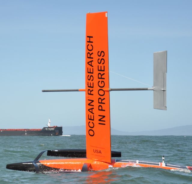
2.6.1.3 FASt
FASt is a 2.5 m LOA (length overall) autonomous sailing boat. The design is inspired in the hull shape of offshore racing sailing boats, with a deep keel and twin rudders. The deck was kept flat to facilitate the installation of hardware, solar panel and water tight connectors for attaching external instrumentation. The hull was built with epoxy resin and a sandwich of carbon fibre, honey comb core and fibre glass. The keel was laminated with a carbon fibre skin around a polyurethane foam and a hard wood core. A 20 kg lead ballast was built from sheets of lead glued with epoxy and covered with a fibreglass skin. The keel is attached to the hull by locking it in a central keel box across the hull.
Figure 41 displays the FASt.
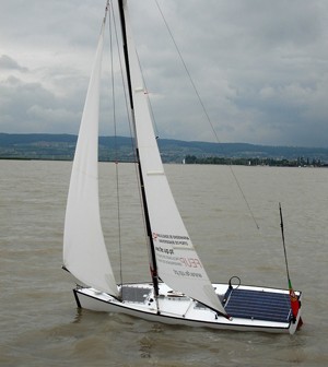
2.6.1.4 ASN Datamaran
Autonomous Marine System delivers a global platform for ocean observation using intelligent sensor networks powered by Datamaran. Datamaran is a catamaran with a length of 2.5 meters, a width of 1.7 m, a mast height of 2.3 m and a mass of 85 kg with full payload. For the communication system it has an iridium modem, cellular networks for low cost and high bandwidth close to shore. Datamaran has two types of propellers: the wind with a self-trimming rigid wing sail, and an electric propeller available for tight manoeuvring and added space.[Autonomous Marine Systems, 2015]
Interesting in this project is the rigid wing sail and its dimension, from which we can get ideas. Also the positions of the sensors are well chosen, but we cannot confront with our prototype because Datamaran is multi-hull and the available surface is different from our mono-hull boat.
Figure 42 displays the Datamaran.
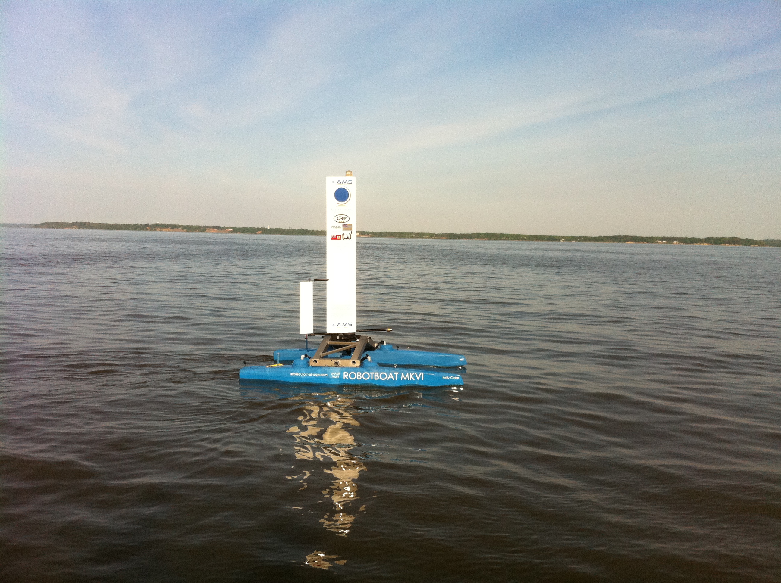
2.6.2 Platforms
After comparing related work in terms of the boat we have investigated and the related platforms which were installed to control the autonomous component selection of our design. These components can vary but are crucial not only for optimal manoeuvres but this will define the principle components to while on extensive missions. The platform is also used to send and receive information in a selection of systems and although not considered for our rigid-wing sail, it must be fully understood and considered for the final autonomous sailboat product.
2.6.2.1 Raspberry Pi
The Raspberry Pi from The Raspberry Pi offers live debugging for quick development while in operation. The schematic of the boats control circuit can be seen below in figure 43. M1 and M2 denote Motors, R1-3 are AS5040 chips. The Raspberry Pi is the main control unit reading the sensor data converted by the Arduino and controlling the motors of sail and rudder by its GPIO pins. GPS is connected directly via USB. 700Mhz ARM processor it runs a full Debian Linux environment.
Communication for programming and debugging purpose is established over Wi-Fi with a USB dongle (Netgear N300). Although the Pi is good for fast iterations in software development there is no easy way to read the PWM signals from the wind and motor rotation sensors. To overcome this problem the Arduino reads the PWM signals and transmits the current sensor values via a serial connection to the Pi. [Luc Jaulin Fabrice Le Bars, 2013]

2.6.2.2 PSC/HMI & CAN Bus
The system is actually composed of two major parts, the Programmable Servo Controller (PSC) and the HMI, which displays sensor information and allows the skipper to activate the joystick or to use the autopilot. The communication between the bus and the HMI tablet uses Bluetooth, whereas internal communication is made entirely using the CAN protocol. Its behaviour can be assimilated to a closed-loop system. Information, which comes from the environment as any human input, has influence on the actuators, that is to say the system will be able to perform automated tasks.
The programmable servo controller PSC is a key component of the system and can do the work of an autopilot course computer, which can steer to wind or compass when associated to the corresponding sensors. The PSC board contains a microcontroller, power electronics for an electric motor (ram or winch), an electric clutch and the power supply including filter circuits. Various interfaces for rudder angle sensor, joystick and control keyboard already exist and, in future version.
The HMI, programmed for Android by using the Android Software Development Kit (SDK) tool for Eclipse, contains different areas in addition to textual information, some data, such as wind orientation and speed, compass and rudder angle, is also displayed in graphic form to allow a better understanding of the environment. A last area acts as a virtual keyboard to switch between autopilot and joystick mode and the user can modify the course to steer. The graphical layout of the HMI is realised in XML language and could be easily modified to fit needs of specific users. This results in a system (joystick, tablet display, extra keyboard, etc.), compatible with different disabilities, while still being usable by sailors without any disabilities. [Luc Jaulin Fabrice Le Bars, 2013]
Figure 44 displays the HMI/PSC Control Modulus.

The requirement for CAN bus architecture came from the multi sensor and actuator problematic and the cabling and communication complexing with each added element of the autonomous boat project. The CAN protocol is now widely available and starts migrating into many non-automotive applications. This open standardised high layer protocol provides a reliable message exchange system between various nodes.
The system architecture is based on Arduino compatibility and uses a CAN bus interface card we call the CANinterfacer. The CANinterfacer is compatible to an Arduino with a CAN shield on top. This on purpose designed board uses an ATMEGA32U4 microcontroller as do the Arduino Leonardo and Micro. It is small in dimension and can be programmed by USB using the Leonardo bootloader and the Arduino IDE. It can be powered from the CAN bus by an onboard switching power supply accepting from 7 to 32 Volts, most of the I/O pins are available for local connections.
In the system shown below in figure 45, a group of elements (actuators, sensors, HMI elements, etc.), wired to a CANinterfacer, becomes a CAN node. That is to say, each CANinterfacer typically uses Arduino libraries to convert input from various sources, for example analog inputs, NMEA 183 or I2C connected sensors, into a CAN messages. Putting a CANinterfacer between the new hardware and the bus to integrate it as standard node gives great flexibility. [Luc Jaulin Fabrice Le Bars, 2013]

2.6.2.3 ARRTOO
The control system will be based on an architecture developed for previous sailing robots built by Aberystwyth University. The system uses two microcontrollers: one for control of sailing, monitoring sensors etc and one for managing (non-payload) data-logging and communication via the Iridium satellite network and ZigBee during launch and recovery. This split ensures that accurate control is maintained during extended data communication periods. A separate Iridium modem for the payload system reduces difficulties when integrating new payload systems and decreases the coupling between control and payload systems and helps to prevent faults in one system affecting the other. There is also provision for an additional communication device and AIS and RADAR systems to be installed. There is provision for up to eight payload devices, connected to the payload management micro- controller by either NMEA 0183, USB, RS232, I2C or SPI protocols as shown the figure below 46. [Luc Jaulin Fabrice Le Bars, 2013]

2.5.2.4 ATIRMA
The sailboat controller is a commercial credit-card size board based on a AT- mega1281 microcontroller running at 8MHz. The microcontroller integrates 8KB of SRAM for data, 128 KB of FLASH memory for program and 4 KB EEPROM. The board provides several UARTs, an I2C bus, a micro SD card reader, a real-time clock, a three-axis accelerometer and several other sensors for measuring, for example, the board temperature or the battery level.
This board is ready to accept external hardware modules like a GSM/GPRS modem, a GPS receiver or different XBee RF communication modules. It has 5V and 3.3V on-board regulators. It is powered from a 3.7V 6000 mAh Li-Ion battery and consumes 9 mA under normal operating conditions. Suitable photovoltaic panels can be connected directly to the board to recharge the main battery.
The ATIRMA hardware list [Luc Jaulin Fabrice Le Bars, 2013] can be seen below in the table below.
| Hardware List |
|---|
| 8-bit Microcontroller |
| XBee PRO 868MHz RF Module |
| GPS Receiver |
| Electronic Compass with Inclinometers |
| Wind Vane |
| Current Sensor |
The main software elements are the base station control application and the software that runs on the 8-bit microcontroller on board the sailboat. The base station is a Linux application with a Qt front end that relies on the libXBee library to support the radio communications using the XBee radio modules. Using the graphical user interface (GUI) it is possible to add, edit or delete a sequence of waypoints, just by clicking on a Google map, to define a route for the sailboat. The interface displays telemetry data received from the sailboat relative to sensor readings or position, bearing and speed of the sailboat. It is also possible to modify some thresholds and parameters like the frequency at which the telemetry packets are remitted or the minimum frequency at which the bearing selection function must be invoked. [Luc Jaulin Fabrice Le Bars, 2013]
Figure 47 displays the ATIRMA System Architecture.

2.6.3 High Level Control Architecture & Logarithms
Multi-agents missions can be variant from patrolling in predefined area, reaching specific destination, following or monitoring specific object, go back to home harbor, etc,. Distribution of missions between agents can be done by the agents themselves or by CTPS.
Figure 48 displays Mission Distribution Flowchart.

Each agent has independent priority queue of missions, in form of a maximum heap. Once a new mission is given to an agent, it starts at the bottom of the queue, and then works its way to the correct place in it. The agent updates its own active mission once given new mission. Updating mission can be given by the agent itself or by the CTPS. Along with mission priority, the agent receives top priority concept state: Change mission using only mission priority, or replace current mission regardless to mission priority. The default and basic mission is trajectory tracking loaded beforehand to the agents. Mission distribution module flow chart is presented in the figure above, 48. [Luc Jaulin Fabrice Le Bars, 2013]
Some missions, such as following mother ship or sending vehicles ahead mother ship, are given with missions priority to the CTPS by an outside source. The CTPS receives or decides by itself the number of agents required for each mission, decides which agents would be best for the mission and gives the mission to the appropriate agents. The choice of each agent for every mission is based on the priority of the current mission for each agent. Agent with minimal distance from agent’s current position to starting point mission would be preferred by CTPS. The CTPS can also save missions with relatively low priority to the current mission. When an agent complete mission it notifies the CTPS, so CTPS can allocate the agent to start working on a mission that has been saved. [Luc Jaulin Fabrice Le Bars, 2013]
Figure 49 displays Mission Managed by CTPS.

2.7 Conclusion
There is great deal of detail in this chapter which has been quantified and specified to find solutions for our boat design. All our learning outcomes will be further developed in the 7.0 Project Development section. The State of the Art has allowed us to derive the best possible design for the boats requirements, below is a list of features our boat should have as an end product.
- Sailboat
- Hull ⇒ Vee/Rounded bottom
- Keel ⇒ Bulb keel
- Rudder ⇒ Spade rudder
- Wing-sail ⇒ Airfoil NACA 0012
- System
- Sensors
- Wind ⇒ AMS AS504X Encoders
- Compass ⇒ Honeywell HMC5883L
- GPS ⇒ SparkFun Venus GPS
- Battery ⇒ Li-ion
- Solar Panel ⇒ Polycrystalline solar cell
Although some of these are not getting taken into consideration it is vital to highlight the possible components for future upgrades, which is dependant on product improvement and the client. The system that we will adopt on our boat is a battery and solar panel. These components will allow the sailboat to function at the simplest level on its own accordance. The next chapter will point out how we organised ourselves along the project. The aim is to manage our valuable time and resources over the entire duration of the project.
3. Project Management
3.1 Scope
The scope for our project is an autonomous monitoring system, which is deployed for extensive periods of time in aquatic environments. The project concentration will be solely lie in the development of a functioning sailboat for the autonomous system platform. The boat will be deployed in several environments, to ensure this and a high quality product, we must:
- Fully sustainable, using negligible resources to function.
- Complete user manual.
- Safety for both user and animal/marine life as it may impact when deployed.
In addition, the following deliverables have to be developed, documenting the project´s process and achievements: this report, a paper, a leaflet, a poster and a video.
The user manual will incorporate the use of the hull and sail, as our main focus is on this although the finished product will be a fully functioning autonomous monitoring system. This must be taken into full consideration when the boat is being designed.
The prototype must succeed in all requirements and functionalities to be deemed successful, allowing it to work and be controlled unmanned is not our objective but as stated before all considerations must be made for this factor. The detailed technical requirements towards the prototype are listed in section 1.5 Requirements. It is tried to fully comply with the requirements during chapter 7.0 Project Development.
The WBS of the project can be seen below, this is subcategorises the project deliverables allowing the customer to see the end goals and objectives over the timescale. This hierarchal diagram shows all measures that must be addressed for project successes.
Figure 50

The way we organised ourselves around the various deliverables and tasks can be seen in the subchapter 3.2 Time and in the planning part.
3.2 Time
Time management is a key matter for the project. It accounts for the deliverables to the clients and incorporates the entire team to achieve the end goal. Shown below the deadlines for deliverables, which were predetermined by the EPS coordinators:
| Deliverables | Deadline |
|---|---|
| Hand in list of materials | 27-03-2015 |
| Upload interim report and presentation | 05-04-2015 |
| Interim presentation | 09-04-2015 |
| Upload the Final Report, Presentation, Video, Paper, Poster and Manual | 12-06-2015 |
| Final Presentation, Individual Discussion and Assessment | 18-06-2015 |
| Make final corrections to the report and wiki, according to received feedback | 26-06-2015 |
In addition to these deadlines the team has prepared additional deliverables for our client:
| Deliverables | Deadline |
|---|---|
| Storyboard | 12-03-2015 |
| 3D Computer Model | 23-03-2015 |
| Styrofoam Model | 11-05-2015 |
| Prototype/Finalised Model | 12-06-2015 |
Based on these deadline tables, an outline can be portrayed for the quantity of work that must be done for the project. The work assignments have been specified and categorised according to the deadline and durations of the deliverables. These tasks are subject to change as computing an accurate plan for such a long duration is demanding, therefore the Gantt chart has been repeatedly revised as the project proceeded.
Figure 51

3.3 Cost
Controlling the project budget is vital for the success or failure, this parameter must be strictly monitored throughout the project. The budget for this project is 500 € and is provided by LSA. The project includes direct and indirect costs, shown below:
- Direct – The model and prototype expenses through materials, these will be researched and chosen strictly to maintain a large safety margin and quality design.
- Indirect – EPS cover these working condition costs which incorporate facilities and staff such as technicians, professors and supervisors salaries.
Figure 52 displays the list of resources: Human and Material.

Figure 53 shows a grouping of the costs for the types of resources.

Figure 54 displays the costs for the resources per month.

3.4 Quality
Quality is essential in throughout a products life cycle, from planning to manufacture it contributes several variables to the satisfaction of customers, stockholder, investors and even employee’s. The most important thing for our company is an on going or continuous improvement of processes and material quality to ensure that our sail is at every time at the state of the art. For this it will be necessary to even consider the smallest changes and be also open for new ideas that might change the whole design.
3.4.1 Process quality
- It begins with innovative designs that we will find the basis of in ISO 12215:2002. The ISO standards ensure a quality product on an international platform this reduces cost and allows the product to enter new markets overseas. Quality control measures will be implemented, both human and technical aspects will be input to the entire process. In particular the manufacturing stage, as inspections will make sure products are finished to the highest precision.
- Group meetings will take place on regular occasions to address any problems that arise over the coming months of the project from over and under allocated tasks to cost management problems.
- Supervisor meetings will also take place weekly on Thursdays. During these meetings, we will provide the supervisors with the newest achievements on the project and on the other hand we will get support when needed. This will ensure that our product will at the end be a fully functional deliverable for our client that meets an adequate standard of engineering.
3.4.2 Product quality
- Testing the products in the functional tests will certify and validate the quality for the customer and the market. Furthermore it will verify the properly done design and usability in different water bodies. The testing procedure will commence on going through the product development. All testing circumstances will be strictly monitored to guarantee accurate results and figures. The testing stage will either confirm or de-confirm if the product was successful in completing all requirements for the client while finding solutions to these requirements.
- Costumer and client opinion about product quality is another aspect of quality that will have a profound influence on our work. The final product has to meet at the end the needs of potential customers as analysed in the marketing chapter but also the requirements set by our client at the beginning of the semester. To ensure the satisfaction of the client we must show him on regular basis our work and design ideas and wait for his approval to proceed. It is essential to meet in the first place the needs of our client and after this of future potential customers as Eduardo Silva is providing the money.
3.5 People
The academically integrated and international Team 5 opted for allocation and delegation of tasks suited to individual strengths within the project. The team members are shown below, followed by a task allocation list:
Roberto Giordano ⇒ Gary Jonathan Rabone ⇒ Marc Navarrete Hill ⇒ Imre Asztalos ⇒ Thies Gunther
Figure 55

The work distribution has been allocated singularly, pairs and in some circumstances the entire team due to severity of the task. The severity of the task is dependant on the work load and the deadline date. Distributing these tasks among several members of the team will allow the team to make deadlines and if additional assistance is required members can be shifted to complete all tasks on time.
We enclose in this section the Role and Responsibly Assignment Matrix, also called RACI matrix. The RACI matrix specifies the type of relationship between the resource and the activity : Responsible , Accountable , Consulted , Informed . With this tool you see ” who does what “ within an organisation . The matrix assets / resources , or the RACI matrix , can be used for the modelling of business processes of the base. Introducing a sequence of activities and crossing them with the actors of the process , you can represent a flow chart of the procedure to be followed .
- 'Responsible' is the one who performs the work. In other words he/she is the ‘doer’ of the task or activity.
- 'Accountable' is the person or role who has the final authority and accountability to a given task.
- 'Consulted' are the people/roles who are consulted and taken advice from before and during performing the task.
- 'Informed' are the people/roles who are informed after the task is completed.
Figure 56
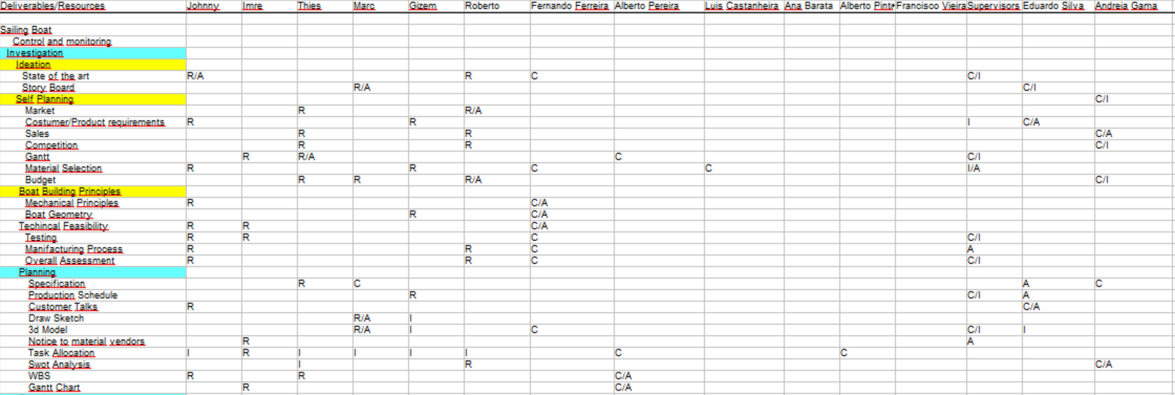
Figure 57
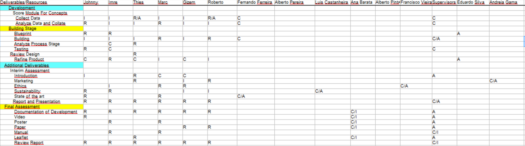
3.6 Communications
Communication in team work conditions can define success or failure from oral, written and nonverbal communication, everyone must be involved. Each individual member of our group has a particular way of connecting and transferring information.
Figure 58

(1) Primarily our communication is orally, during face-to-face meetings where agendas and targets are clearly highlighted as topics of interest. In these circumstances healthy discussions and debates can take place and this usually overruns the meeting times but a clear goal has been achieved afterwards. Meetings take place in ISEP facilities and also in other locations pending to members attendance.
As a group, Team 5 attend weekly meetings with the EPS supervisors. Preparation is required for the meetings, usually questions which are uploaded prior to the meeting time. One member of the team is selected as the speaker to ask these questions to the supervisors. The meeting is recorded via audio and written, later these are collated into the group logbook. Post meeting discussions can be arranged if either the meeting overruns or questions have yet to be answered.
(2) Written communication is used mainly in unsocial hours, when team members or advisors are unable to meet and must contact over the following platforms, from the EPS standpoint and for our clients LSA.
(3) Finally, nonverbal communication is used mainly in team meetings where a team members is confident and trust in each member as it is an obligation to complete the tasks for each deadline. This is usually conveyed in group meetings when member are disconnected from the matter at hand.
- Communication Table
| What | Who | How | When | Why | To whom | Encode/Decode/Notes |
|---|---|---|---|---|---|---|
| Interim Presentation | Team | Orally, Prezi | Once;9th April | Compulsory, Midterm feedback | Supervisors, EPS students | Visual presentation, english |
| Weekly team meeting | Team | Meetings | Every week | Transfer information | Team | English, safe progress on Facebook group |
| Final Report | Team | Email, wiki deliverables | Once, 12th June | Compulsory deliverable | Supervisor, client | English, pdf document |
| Progress to client | Jonny | Email, website, meeting | Monthly | Keep updated | Eduardo Silva | Digital basis, english |
| Calculations and design proposals to Fernando | Roberto | Meeting, email | Weekly | Ensure correctness | Fernando Ferreira | Excel,paper based, english |
| Weekly supervisor meeting | Team | Orally | Every week | Update of progress | Supervisors/Benedita | Orally, wiki page, english |
| Changes in the project | Eduardo Silva/client | Orally,email | Unregular | New ideas, objectives, requirements | Supervisors, team 5 | Orally, English, Portuguese, drawing |
3.7 Risk
Risk management is the act or practice of dealing with risk. It includes planning, identifying, analysing, responding strategies, and monitoring and controlling the risk factors. Risk should be closely coupled with key project processes, including but limited to: overall project management, scope, schedule, quality and time. (Project Management: A Systems Approach to Planning, Scheduling, and Controlling By Harold R. Kerzner)
Below are the possible risk factors we might face during our project:
| Risk | Consequence | Probability (L/M/H) | Feedback Response | Owner |
|---|---|---|---|---|
| Floatation/Buoyancy problems | Boat might capsize. If the boat design is not sufficient to float and the hull is not sealed properly water may come inside the body of the hull. | (H/0,25) | Double check before putting in water, perform a floatation test in our tank with weights exceeding the required weight capacity of the boat. Also seal the hull with a waterproof sealer and test in a body of water. | Jonny |
| Sail/Hull design is unacceptable | Sail is not creating a great enough lift or breaks. Delay in project for re-design. We are developing a wing-sail/hull and have little experience in the aerodynamic/naval a sector. It is possible that our design doesn’t work as expected. | (H/0,25) | Inspect all possible failures of the wing-sail/hull with every available expertise (i.e Fernando). Try to develop an advanced wing-sail/hull with available materials. | Marc |
| Styrofoam Model does not work | Mistakes in our calculations and design, delay in project. The 1:1 scale Styrofoam model is incompatible due to design and features incorporated | (L/0,05) | Refine design of the hull using calculations and ensure pristine testing circumstances | Roberto |
| Non-functional teamwork | Delay in project tasks, milestones are not reached. We might need to do re-organisation of tasks | (M/0,15) | If it is a serious situation, the person´s tasks will be redistributed among the remaining team members. | Roberto |
| Late for Deadlines due to incapability of team mates | Too late hand in deliverables, less good grades or delay in total project. | (M/0,15) | Ask the supervisors for an extension after explaining the problem that occurred. | Thies |
| Miss the Deadline due to technical problems | Too late hand in deliverables or less good grades or delay in total project | (M/0,15) | Ask the supervisors for an extension after explaining the problem that occurred. Save everything twice. | Imre |
| Materials are not as expected | Delay in project, decrease in quality, cost increase. Calculations were incorrect thus incorrect materials were selected for the Prototype. | (L/0,06) | Ask the supervisors for extension for delivering the prototype, organise a new source for materials that delivers express. | Roberto |
Risk: Buoyancy Problems
| Probability⇒ Impact | Very Low (0,05) | Low (0,3) | Moderate (0,5) | High (0,9) |
|---|---|---|---|---|
| Very Low (0,05) | ||||
| Low (0,1) | ||||
| Medium (0,2) | ||||
| High (0,5) | 0,25 |
Risk: Sail Problems
| Probability⇒ Impact | Very Low (0,05) | Low (0,3) | Moderate (0,5) | High (0,9) |
|---|---|---|---|---|
| Very Low (0,05) | ||||
| Low (0,1) | ||||
| Medium (0,2) | ||||
| High (0,5) | 0,25 |
Risk: Foam model does not work
| Probability⇒ Impact | Very Low (0,05) | Low (0,3) | Moderate (0,5) | High (0,9) |
|---|---|---|---|---|
| Very Low (0,05) | ||||
| Low (0,1) | 0,05 | |||
| Medium (0,2) | ||||
| High (0,5) |
Risk: Teamwork Problems
| Probability⇒ Impact | Very Low (0,05) | Low (0,3) | Moderate (0,5) | High (0,9) |
|---|---|---|---|---|
| Very Low (0,05) | ||||
| Low (0,1) | ||||
| Medium (0,2) | ||||
| High (0,5) | 0,15 |
Risk: Missed Deadlines/ Missing Persons
| Probability⇒ Impact | Very Low (0,05) | Low (0,3) | Moderate (0,5) | High (0,9) |
|---|---|---|---|---|
| Very Low (0,05) | ||||
| Low (0,1) | ||||
| Medium (0,2) | ||||
| High (0,5) | 0,15 |
Risk: Miss Deadlines/Technical
| Probability⇒ Impact | Very Low (0,05) | Low (0,3) | Moderate (0,5) | High (0,9) |
|---|---|---|---|---|
| Very Low (0,05) | ||||
| Low (0,1) | ||||
| Medium (0,2) | ||||
| High (0,5) | 0,15 |
Risk: Material Problems
| Probability⇒ Impact | Very Low (0,05) | Low (0,3) | Moderate (0,5) | High (0,9) |
|---|---|---|---|---|
| Very Low (0,05) | ||||
| Low (0,1) | ||||
| Medium (0,2) | 0,06 | |||
| High (0,5) |
3.8 Procurement
The development and manufacture of a sailboat includes a vast array of components and materials to which we have the responsibility of sourcing quality suppliers for the design. A quality to cost comparison must be made and a final material or component must be selected that will fit the bill of our project. Due to restrictions we were only allowed to use local Portuguese shops and websites however, our client Eduardo Silva from LSA, has stated international purchases may be acceptable but only after his authorisation.
Figure 59 displays the core criteria for our procurement upon which we will evaluate the suppliers.

Taking these criteria into consideration, we worked on a scheme to evaluate our suppliers upon. The result will be a comprehensible and well-grounded decision where to purchase from.
Figure 60 displays our supplier evaluation that we wanted to use.
Due to some short runs in time, the restriction from the advisors to purchase only in Portugal and the fact that we got suggested suppliers from them, we focused on these suppliers or were satisfied if we were at least able to find suppliers. The biggest problem we faced was the language barrier, as non of us speaks Portuguese. It was hard for us to find the right components and even though the internet offers various solutions it is still hard to filter the right one without understanding the website.
Lastly in relation to the purchasing costs, we can state that once on an international market, the autonomous sailboat can be developed at lower costs due to higher demands thus affordable supplier demands. This will improve revenue in our company by reducing costs over time while growing our quality exponentially. This must all coordinate with the compliance of the product to the customer, for filling all requirements on every product delivered. Also we will decrease our scrap by getting more routine during the production processes.
3.9 Stakeholders management
Stakeholder management is the process of managing the expectation of anyone that has an interest in a project, will be effected by its deliverables/outputs or has the power to change the project. In our project we have several stakeholders, with different expectations. We try to analyse in this section the expectation of every stakeholder. Stakeholders are for example all the teachers of the EPS, all the supervisors, our client Eduardo Silva, the team members and also the university. By defining the stakeholders and analysing their different relation and expectation towards our project we can create a strategy to build up sustainable and efficient relationships that will satisfy all participants. Apart from the close parties that have interest in our project, we also have teachers in various subjects as Project Management, Marketing, Ethics, Sustainability. All the professors teach us the basics to write the report but have a low interest in the project itself. At last we have the university as a stakeholder that is providing the opportunity to do an EPS semester at ISEP.
| Stakeholder | Role | Possible Expectation |
|---|---|---|
| Team members | Project Development | Improve our skills, get to know new cultures while having international team mates. |
| Fernando Ferreira | Project Advisor | A good knowledge of the mechanical principles as the basis for boat design. |
| Alberto Pereira | Project Management | Accurate use of the techniques for Project Management. |
| Luis Filipe Caeiro Castanheira | Energy and Sustainability | A good realisation of the sustainability principles involved in the design and in the development of the project. |
| Ana Barata | Communication and Portuguese | Reasonable understanding of the basics in Portuguese language and how to communicate our results to other stakeholders. |
| Alberto Peixoto Pinto | Team Building | Correct division of the roles inside the team and a good understanding of the strengths and weaknesses of each team member. |
| Andreia de Sousa Taveira da Gama | Marketing | Deliver a well rounded knowledge of the market at which we intend to enter. |
| Francisco Marques Vieira | Ethics & Deontology | Consciousness of the basic principles of Ethics & Deontology at the bottom of engineering projects. Applying liability principles in all aspects of engineering developments. |
| Supervisors | Follow and supervise project steps | Respect the deadlines and do a successful project. |
| Eduardo Silva | Client | Develop a prototype in respect of some constraints. |
| ISEP | University | Responsibility as members of the university and respect the culture at university. |
| Benedita Malheiro | Chief Supervisor | Good and successful project. |
Figure 61 displays graphically how we want to manage our stakeholders

Our four concepts for the stakeholders management are to keep satisfied, manage closely, keep informed and monitor. These concepts are influenced by the power and the interest that the stakeholder has in our project.
Keep satisfied: This will consist of the fact that we will try to reach the expectation that the stakeholder has towards us as members of the project-team but also on the project itself. Therefore we need to analyse the stakeholders interest and also review ourselves in our project progress.
Manage closely: The concept of manage closely displays our most important stakeholders. They have a high power in changing our requirements and objectives and they also have a high interest in the project success. For these group we will try to keep them weekly and/or monthly updated by meetings, emails and work with them together as we proceed with our tasks.
Keep informed: Stakeholders in this segment will be kept updated by email or indirect via managing our homepage. Although they have a high interest, they have a low power which leads to the fact that we should have less commitment to meet with them and spent time in their management.
Monitor: All stakeholders in this segment have to be monitored in respect to their satisfaction. For example any teacher in the subject has to be satisfied with the work done in the chapter of the report and also participation during class but on the other hand the project itself has a low interest for them. This leads to the fact that we will rather monitor that we perform well in their class and provide them with the filtered information needed for their specific part in the project.
3.10 Task Management
Figure 62 displays the tasks of the 1st week

Figure 63 displays the tasks of the 2nd week

Figure 64 displays the tasks of the 3rd week

Figure 65 displays the tasks of the 4th week

Figure 66 displays the tasks of the 5th week

Figure 67 displays the tasks of the 6th week

Figure 68 displays the tasks of the 7th week

Figure 69 displays the tasks of the 8th week

Figure 70 displays the tasks of the 9th week

Figure 71 displays the tasks of the 10th week

Figure 72 displays the tasks of the 11th week

3.11 Conclusion
A projects success is dependant on team organisation and logistics. In order for these to be produced, properly allocation must be taken in the team atmosphere ensuring trust and understanding of every team member role and more importantly each individual goal. Balance is key when delegating and deciding tasks. We tried to involve everyone with there strengths and even weaknesses to produce a quality product in the desired time frame and budget. Overall our goal is to deliver a product to the client with minimal risk and with strict rules on procurement while involving all stakeholders in the progression of the project. In the next chapter we are going to understand where we can position our product in the market and also to understand the competition involved. As marketing is a key factor for a successful implementation of products, we want to ensure to find the best strategies for the autonomous sailboat.
4. Marketing Plan
4.1 Introduction
Oceans cover 71% of our world surface. [National Oceanic, Atmospheric Administration, 2015] For many years the sea was mainly navigated and explored, but nowadays humanity possesses the technology to analyse the sea and find resources for energy and research functions. This new approach of investigating offshore about the sea´s diversity and its unforeseen fortunes is a great opportunity for unmanned sailboats. In the process of a continuous development, the demand for accurate ocean sampling is continuously growing in order to provide a better understanding of the complex sea environment. An autonomous sail boat can satisfy the needs of many companies in this way, with several sensors for several needs. Our goal of the marketing plan is to find a potential market by analysing competition, market segments and potential customers for our product. The key for a successful product implementation will be to find a niche or spot in the market that has not been fulfilled yet and on the other hand will create a for the customer recognisable benefit.
An easy way to display a successful marketing process is shown in Figure 73

To have a successful marketing process and strategy we will have to understand our product itself. Our boat will fulfill different purposes offshore and will be capable to use a great variety of sensors and cameras. To specify the effectiveness of our segmentation and positioning later on as well as our potential customer analysis, we have to bear in mind all different product dimensions. It is important that the customer recognizes the his personal benefit. “The main target of marketing is that the selling process is redundant. The object is that you understand the customer and their needs in a way that the developed product matches perfectly with these and will sell itself.”[Peter Drucker] The next figure will display what kind of product dimensions we have to take into consideration while analysing the customer needs.
Figure 74

The dimensions of the product that we have to keep in mind for any marketing strategy are containing aspects of the boat that can be offered to any customer apart from just the boat itself. The core product or core customer value we sell is a sailboat that can sail autonomously and stay in a specific region for a defined amount of time. Apart from this we also have to take into consideration the need of design aspects, quality, brand name and features, which are part of the “Actual Product”. It might be important for our customers to have a special kind of design. Mainly because our product will be operating in the name of the business and could cause public interest. Furthermore we will have to ensure a unique and high level of quality. This is important because our customers will have to rely on the correct functioning of the product as it will be not in direct reach of humans when on its mission. Next we need to manage to build up a certain brand name to attain loyalty and bonding towards our products. As business to business is a hard market with a low number of customers, we need to attain good relations. We want to achieve this loyalty by offering a good after sales service and also by giving prior instructions in seminars. Also flexible payment possibilities can attract customers. All these aspects are essential for a good marketing campaign.
4.2 Market Analysis
“A market is a virtuell or real place where the offer of a product meet with its demand which concludes in a price.” [Harley Krohmer Christian Homburg, 2009]
4.2.1 Macro Environment
The macro environment is composed by major external and uncontrollable factors that influence the decision making process of an organisation and affect its performance and strategies. We can study the macro environment of our product with a “P.E.S.T analysis”, composed by political, economic, social and technologic factors.
Figure 75

4.2.1.1 Economical environment
We focus our analysis in this chapter on the economical background of Europe and in particular of Portugal. Due to the fact that Portugal is the country in which our brand and company will be founded, it has a superior effect on our first year success. The European crisis was the background of the great recession in Portugal, which was a debt crisis during the years of 2010-2014. This recession was the reason for the country being unable to repay or refinance its governmental debts without the assistance of third parties.
Figure 76 is displaying one of the main results of this crisis, the drop down of the gross domestic product (GDP).
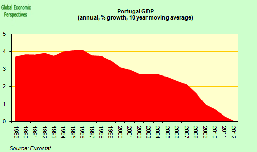
The effect of the crisis on the Portuguese economy can be for example seen in the expenses for research and innovation system over the last decade. It constantly increased its investment in research at a remarkable average annual real growth rate of 7 % between the years 2000 and 2007. However, with the beginning of the recession, the R&D intensity in Portugal decreased by an average of 0.16% during the years of 2008 to 2011. [European Commission, 2015] In the table below we can see the performance of Portugal in research, innovation and competitiveness. The indicators relate knowledge investment and input to performance or economic output throughout the innovation cycle.
Figure 77
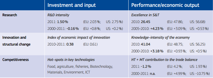
In addition to this is the “Research and Development” intensity projection Figure 78
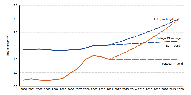
Focusing on energy production, according to the European Renewable Energy Council, the installed capacity in 2009 was approx. 250 MW. This included La Rance in France that has an annual production of 550 GWh. In terms of electricity production generated by the sector, ocean energy estimates the following: 0.62 TWh in 2010, 8.94 TWh in 2020, 150 TWh in 2030, 549 TWh in 2040 and 645 TWh in 2050. Focusing on Portugal in October 2011 Principle Power deployed a full-scale prototype WindFloat 5km off the coast of Aguçadoura.
In terms of the economical aspect our analysis shows that the recession is still present in Portugal. The unemployment rate in Portugal is on a high level compared to former years but this also means a higher potential for us to find employees. Lastly we are convinced that the crisis is a chance for us and believing in the forecast, we think that the economy is about to get better.
Figure 79
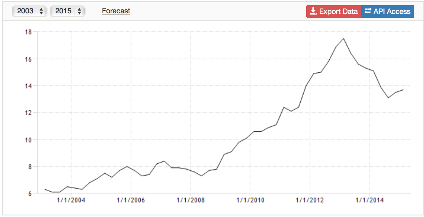
Figure 80
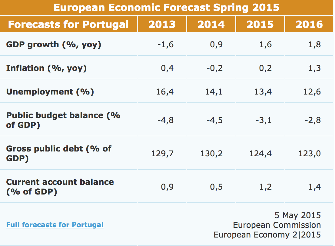
4.2.1.2 Technologic Environment
There are two factors included in the technologic environment of an autonomous sailboat, the marine technology background and the improving robotic background. As seen above in Figure 78 the first aspect is expanding due to inexhaustible human needs to find new resources. In terms of the second mentioned background we can state, according to the international federation of robotic in 2013, that robot sales increased by 12% to 178,132 units. This is by far the highest level ever recorded for one year.
4.2.1.3 Political environment
Political backgrounds influence organisations in many ways and are able to create threats and opportunities for them.
The European Union provides an integrated maritime policy that is supposed to be a more coherent approach to maritime issues, by an increased coordination between different policy areas. The “Blue Growth” is the long term strategy to support sustainable growth in the marine and maritime sectors as a whole. Seas and oceans are drivers for the European economy and have great potential for innovation and growth. It is the maritime desire to achieve the goals of the Europe 2020 strategy for smart, sustainable and inclusive growth. The strategy consists on three components:
- Develop sectors that have a high potential for sustainable jobs and growth.
- Essential components to provide knowledge, legal certainty and security in the blue economy.
- Sea basin strategies to ensure tailor-made measures and to foster cooperation between countries.
In June 2014, the European Council adopted a Maritime Security Strategy for the global maritime domain. The objective of this strategy is to provide a common framework for relevant authorities at national and European levels to ensure coherent development of their specific policies and a European response to maritime threats and risks. The second aim of such a strategy is to protect EU's strategic maritime interests and identify options to do so. Such a framework will provide the context and ensure consistency amongst different sector specific maritime policies and strategies. Most importantly it will significantly strengthen the link between internal and external security aspects of the maritime policy of the EU and civil and military cooperation.
To strengthen the economical and technological environment in terms of further research and development expenses, the European Union intended 21.46 billion euros for the period of 2014 to 2020. This money is targeted to improve the economic competitiveness and innovation of Portugal.
4.2.1.4 Social Background
In the 21st century the interest of the society has changed in some ways. Today more and more people and also companies have concerns about the climate change and related to this green energy. This is on the one hand implemented by governments that restrict the carbon dioxide emissions of fabrics and also by an enlarging number of scientific articles published in daily newspapers or even with documentaries on climate change and its consequences (i.e. “An Inconvenient Truth” by Al Gore). For this reason our product could be useful to take oceans data for meteorologist, scientists or even for taking data to supervise the quality of the water in terms of eating the fish or going for a swim.
4.2.2 MicroAnalyisis
The Micro analysis, is the analysis of the immediate environment that impacts a business. The micro environment includes considerations related to competitors, customers and suppliers.
4.2.2.1 Competitors
When formulating a business strategy, we must consider the characteristics and strategies of the company's competitors. While in highly fragmented commodity industries the proceedings of a single competitor may be less important, in concentrated market like ours, competitor individualisation and analysis becomes a vital part of our strategic plan.
We can segment our competitors in two groups:
- Similar products, but not yet implemented in the market.
- Different products, that already exist in the market with similar functions.
Autonomous Sailboats
As written in the previous section 2.6 Related Work, several products similar to our already exist. They are not yet implemented in the market and their main focus is not commercial usage, but it is possible that if the market will reveal high profit margins, some of these companies with mature technology will try to enter this segment as well. A good example for this is the FASt sailboat, which was designed mainly for racing. However, this boat can easily be modified for market reasons and due to low entry barriers and a high future growth potential, we think that it is very likely that we will have a growing competition in this segment.
Data Buoys
In this market we can find a great variety of data buoys with different sensors for different applications.
- Satlantic’s LOBO (Land/Ocean Biogeochemical Observatory) is a complete turnkey data buoy monitoring system in sensitive and diverse ecological areas such as estuaries and inland waters.
- TRYAXIS is a data buoy that can measure waves and currents.
- MetBuoy can monitor, record and display wind speed & direction togehter with meteorological data.
- Turbibuoy can monitor, record and display turbidity data in support of water quality monitoring or dredge monitoring operations.
We can individuate in a table strenghts and weakness of these competitors beetween our product.
| Name | Strenghts | Weaknesses |
|---|---|---|
| Data buoys | Mature technology and market. Lower price. Easy to use. Lower risk | Buoys are motionless. Smaller markets area |
| FASt | Appropriate Engineering background. More experience | Design focused on race and velocity instead of stability |
| Saildrone,Datamaran and Roboat | Team composed by expert people. High technology. | Its market will be probably concentrated in USA, different from our target. |
4.2.2.2 Potential Customers
We see our main potential customers in a “Business to Business”(B2B) relation with us. The main characteristics of a B2B market are explained in the following Figure:
Figure 81 displays the main characteristics of business markets.

Despite the preexisting autonomous boat market, our purpose in this section is to identify potential costumers in different sectors of the market.
- Oilrigs. In relation to this sector, our boat could help supervising offshore platforms by using cameras that are mounted to the boat. By doing this autonomously, one employee could monitor all different cameras on the boats at the same time. Today there are around 900 offshore oilrigs in Europe, most of these in the North Sea owned by British companies, and in Italy.[Greenreport.it, 2010]
- Off-shore wind farms. Here a list of the biggest 5 European offshore wind farms and in relation to this one farm from Portugal.
| Name | Position | Total Power (MW) |
|---|---|---|
| Blekinge Offshore | Sweden | 2500 |
| Moray Firth | United Kingdom | 1300 |
| Creyke Beck A | United Kingdom | 1200 |
| Creyke Beck B | United Kingdom | 1200 |
| East Anglia (formerly Norfolk Bank) | United Kingdom | 1200 |
| Wind Float | Povòa de Varzim,Portugal | 150 |
- Metereologic and oceonography industry. For example The National Oceanography Centre (NOC) undertakes integrated ocean research and technology development from the coast to the deep ocean. It provides long-term marine science capability including: major facilities; sustained ocean observing, mapping and survey; data management, and scientific advice. Marine science national capability is provided to the Natural Environment Research Council (NERC). [National Oceanography Centre, 2015]
- National governments. Seas are often the more easy way for clandestine immigration. This happen for example in Italy, with lot of north-african people trying to come to the Sicilian coast. This means poor travel conditions and high-risks for their safety. During the last years a lot of accidents happened where boats sunk and many people died. In 2013 a barge sunk near Lampedusa with the death of 366 north africans. For this reasons a continuous monitoring of the coasts is important. In this case, policy provided the use of helicopters, reconnaissance aircrafts and Predator B drones, which could be seen as competitors.
- Port surveillance. Port areas as well as ships docked in ports are vulnerable to numerous hazardous scenarios and are targets for theft and terrorist attacks. Given the vast size of the perimeters of most port areas, manual inspection of all potential points of entry is infeasible. Currently, a number of port facilities are equipped with video surveillance systems. Our boat could improve a surveillance system giving a continuous monitoring of a selected area.
- Fish Farms. In Europe, aquaculture accounts for about 20% of fish production [European Commission]. Lot of Fish Farms use chemical as hygiene products for disinfection or for environmental control, as antifouling agents for fish cages and medicinal products, divided into chemotherapeutic agents for therapy or prophylaxis of disease, which act on the invading organisms and pharmacological drugs, which act on the target animal. It is fundamental in this field to have an appropriate chemical analysis of the water in which the fish grows.
Figure 81 displays a competition analysis and our desired position in the market. The y axis is the configuration if it is a boat or for example a buoy or just systems to monitor and collect data. The x axis is defined in autonomous sailing boats that collect mainly data or not.

4.3 SWOT Analysis
S.W.O.T. is an acronym that stands for strength, weakness, opportunities, and threats. In these terms a SWOT analysis is an organised list of our greatest business strengths, weaknesses, opportunities, and threats. Strengths and weaknesses are internal factors, which refer to our team. Opportunities and threats are external factors, these are always related to the customer and competitor market. Due to its importance and visualisation any new businesses should use a SWOT analysis as a part of their planning process. This will help, when honestly done, to see where you can improve yourself and also to exploit your full potential.
Figure 83
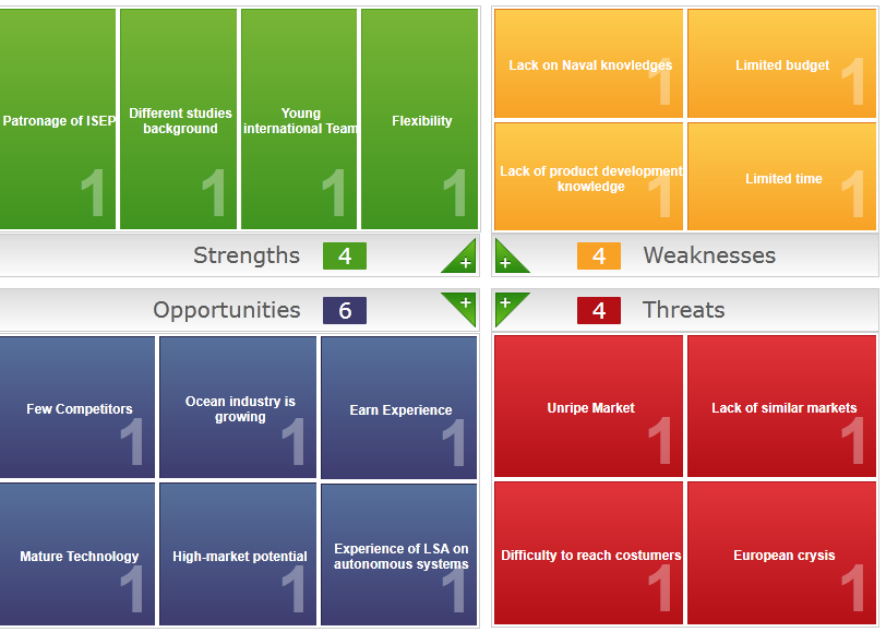
4.4 Strategic Objectives
The reason to define the strategic objectives is to reach a good position on the market. Every start-up business should define their own strategic objectives that they want to achieve in a stated timeframe. This will help to evaluate your success and monitor your defined milestones.
Market objectives for the first 5 years:
- Gain experience in the manufacturing process and about the market reaction during the first year.
- Establish company, policy, logo and name.
- Partecipate to MicroTransat challenge to test and advertise our product.
- Sell the first prototype to a company.
- Build at least five more products.
- Sell five products to different companies.
- Reach the break-even-point fast and ensure to make profit in order to continue production.
- Try to sell our product outside of Portugal.
Figure 84 displays the strategy of “SMART” for the strategic objectives. All our objectives should fulfil these criteria.

4.5 Segmentation
Due to the fact that our product is mainly operating as a data collector and will stay for long term missions in prior defined area, we are opting on a Business to Business (B2B) market with the possibility of also offering our product in the Business to Government (B2G) market.
The process of segmentation is one of the essential marketing processes. It is the basis to decide upon what kind of market segment we want to focus our campaign on and try to position ourselves along the competition.
In the following Figure ##REF:flabel84## you can see one approach to explain what segmentation is, including its various steps. These steps are focused on the process of finding the best market segment and how to position yourself the best way.
Figure ##REF:flabel84##

The segmentation of the market should start by thinking about how you want to approach or reach the interest of your end customer. There are different ways to do so:
- Firstly there is mass marketing. This means you do not differentiate for specific segments in your marketing campaign. Your marketing will be focused on the slogan “one size fits all”.
- Next you can do a niche marketing, which is a specific definition of your product and marketing mix for small sub segments.
- Micro marketing, which is a “one-to-one” marketing where you focus on individualised products and marketing mix.
- Lastly there is the target marketing, which will be our approach. This means that we will adapt our marketing mix and product to a wider defined segmentation.[Philip Kotler, 2010]
After understanding these basics we can continue with our segmentation of the market, which can be done by various aspects. For our analysis we focused on these four criteria:
Figure 86

4.5.1 Characteristics of the companies
To start off we want to give a basic overview of the global ocean market and its various industries. Figure ##REF:flabel86## shows the biggest market segments in terms of overall worthiness in a year respectively to the ocean market. It includes investments and returns depending on the segment. Furthermore we added a table to demonstrate where this global ocean market takes place in the world.
Figure ##REF:flabel86##
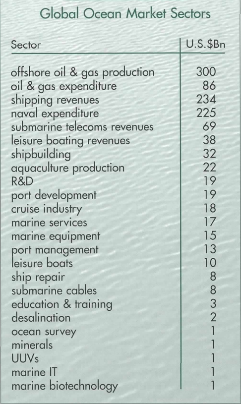
Figure 88 displays the expenditures for the R&D sector in terms of maritime investigations
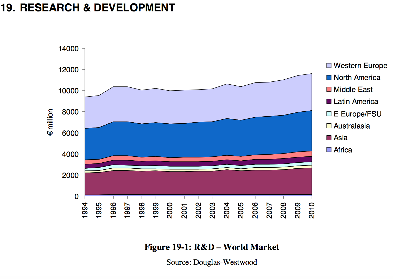
From this Figures we can extract some important information. The total market for ocean related businesses was in 2000 747 billion US Dollars . This means that there is a huge monetary potential in the market. The biggest sector is the oil and gas production but also interesting for us is the amount spent on R&D (19 billion US Dollar). Additionally we can extract that ocean survey expenditure is with one billion US Dollars also really high and underlines our approach for implementing a research and monitoring sailboat.
4.5.2 Geographic Segmentation
Geographic segmentation is a criteria we chose because we want to know the physical location of the potential and actual customers. We would like to get information about where our products is being sold or where it is possible to be sold. This will help us to increase our advertisement and sales mainly in these regions. Our criteria for these segmentations are: investments on research, quantity of potential costumers and employees with naval education background, location of the city/business.
Figure 89
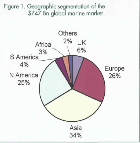
Figure 90 shows the percentage of expenditure for the continents in 2005
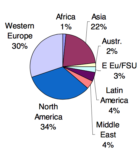
From this data we can extract that Europe and Asia are the biggest markets in terms of the monetary worthiness of marine businesses. The highest financial forces are in the segments related to offshore and gas production, but also interesting for us is the Research and Development (R&D) segment with 19 billion US Dollar. On basis of this knowledge about the market we want to concentrate on Europe. Moreover the members of our team come from different countries in Europe and have a profound knowledge about cultural and language aspects.
Continuing with the geographical segmentation we focused on the fact that we build a sailboat and we have some regional limitation. As a matter of fact it is more likely that our potential customers are located close to the sea, a lake or a river. By investigating on this we focused on seas or big lakes as the need for research boats will be rather interesting for bigger areas that can't be easily monitored. On basis of the location limitation next to the see and the size of the city we searched for the biggest cities in Europe fulfilling these criteria.
| Number | City | Size | Investment |
|---|---|---|---|
| 1 | Iceland/Reykjavik | 121,230 | 25 |
| 2 | Ireland | 1,110,627 | 29 |
| 3 | London | 8,500,000 | 189 |
| 4 | Oslo | 925,228 | 230 |
| 5 | Stockholm | 1,372,565 | 200 |
| 6 | Helsinki | 1,159,211 | 19 |
| 7 | Kopenhagen | 1,181,239 | 30 |
| 8 | Hamburg | 1,800,000 | 300 |
| 9 | Amsterdam | 821,702 | 125 |
| 10 | Antwerpen | 510,610 | 52 |
| 11 | Genoa | 586,180 | 100 |
| 12 | Marseille | 850,726 | 306 |
| 13 | Barcelona | 1,620,943 | 121 |
| 14 | Lisbon | 545,245 | 7 |
| 15 | Istanbul | 9,000,000 | 37 |
Figure 91 displays the relation between population of the city and the expenditure of the country in naval research

Taking in these into consideration, we focused our list on countries by their research and development spendings.
| Rank | Country | Expenditures on R&D (US billion dollars) | Expenditures on R&D Per-capita (US dollars) |
|---|---|---|---|
| 1 | United States | 405.3 | 1275.64 |
| 7 | United Kingdom | 38.4 | 602.78 |
| 4 | Germany | 69.5 | 861.04 |
| 39 | Hungary | 1.7 | 171.61 |
| 12 | Italy | 19 | 316.70 |
As we can extract from the ongoing tables and figures, our target market will be considerably in European countries. Possible cities are Hamburg, London or other cities/countries that have a high expenditure in maritime research. Germany for example spends a lot of money on R&D and in R&D respectively for maritime purposes. Furthermore Hamburg has a high population and many big companies. Undoubtedly Hamburg offers a good connection to the north sea, has a long maritime tradition and provides a great logistic network. Underlining this we can see that the city also has a big international airport, a good railway system , many trucking companies and furthermore one of the biggest harbours world wide. In our opinion when expending our first choice would be the German market. The need of expanding internationally is based on the fact that our product is very specialised and will be mainly interesting for research institutions or big companies that are investigating offshore. Therefore the basis of potential customers is limited in Portugal.
Conclusion of geographic segmentation:
- Target markets geographically after Portugal will be Europe.
- We are European, and we know languages and cultures of costumers.
- Research and development funds are high in European countries, second in respective to the US.
We can also say that the interest of the exploitation for example of offshore wind plants is growing in Europe. Due to the fact that the available land is already intensively used there are strong limitations for the installation of onshore wind farms. The European four year forecast on the prototypical offshore wind farms looks significantly promising and suggests to promote a similar approach in many densely populated coastal countries in the world with high electricity demand.[Gaetano Gaudiosi, 1996]
4.5.3 Way of procurement
In terms of the way of procurement we mean that we want to analyze how our potential customers in the target market segments are processing their buyings, what is there interest in buying, what causes their intention to buy? As a matter of fact Business to Business is mainly done by procurement teams, in our case we focus on decentralised procurement. These teams have certain exceptions on a product and evaluate the product in the buying process upon defined criteria. This means that we will have to convince our customers by quality and functionalities of the product and the process of buying will be larger than normally with private customers. To picture this process we have in the following a typical process of buying a higher monetary product.
Figure 92 displays the stages of procurement when buying B2B.

As we can see, the way of procurement is highly objective and at the stage of receipt offers we will compete with other products who serve the same need. That means that our product dimensions or their purchasing criteria will have to focus on objectively quantifiable and functional dimensions rather than on packaging design for example. Furthermore after sales services are important in this terms because other companies will expect from us to deliver good quality and they will held us responsible when problems occur. The amount of order will be more likely to be small. There is not a high chance of selling big bundles of sailboats to one customer at the same time.
Next we need to analyse the interest they have to buy our product and how they approach us or we get to approach them. The main interest of the potential customer in the segment of R&D and maritime monitoring (for example oil platforms, wind farms etc.) will be the functionality of our product. For this we need to approach them by demonstrating the qualities of the boat and convince them about the necessity of it. For example the Research and Development market segment for maritime products has a total investment volume of 19 billion US Dollars, as already mentioned. This is divided into the following percentages:
Figure 93

Although the defense part of the investments is the biggest component, we can underline the interest of our company in approaching the markets of marine science and oil&gas.
4.5.4 Criteria of usage
For the criteria of usage we have to focus on the technologies that the potential customers may focus on and that we need to address our strategy to. Another aspect is the question if the buyer is the actual user or not and what kind of qualifications our users have. This means that we might have to explain our product and functioning in detail or not.
To begin with, we already mentioned that the main focus of purchase will be in the functionality of the product. It has to have a high value for the customer rather than a solution that we sell. Our customers are basically also the users which means that we will have a direct contact to them. The next open question is, if we should address our product to customers that need a lot or less supportive services. As the following figure will display, we will focus on value buyers. That means that the main interest of the buyer will be the added value for him. We expect that these costumers do not need to get an intensive support service from us. However, to maintain good customer relationships and as defined as high “customer lifetime value”, which is the overall expected value a customer has for the whole existence of its business, we try to offer best services and maintenance of the boats.
Figure 94

4.5.5 Conclusion
Summing up our analysis, we come to the conclusion that our target market segments will be in the Research & Development sector which can be institutions investigating on maritime organisms or structures as well as searching for new oil resources. Additional potential customers are in the segment for monitoring offshore installations such as wind parks and/or oil platforms. For the possible missions that we think our boat can fulfil please check the storyboard. As we mentioned there are high potentials in these segments and we are keen in exploiting these. For doing this the best way, we will analyse in the following chapter the optimal positioning strategy.
4.6 Strategy/Positioning
The target of a good positioning strategy is to adjust the strengths, the requirements and opportunities of the market or its segments with each other. Therefore you follow certain defined steps. Firstly you identify the customer groups towards which you have a unique and special advantage in comparison to your competition. After this you will positioning your product in the market and the perception of the customer. At the end of the process of positioning and differentiation the customer has to know why he should buy our product.
To explain what positioning is, we could say that we will try to pursue a clearly defined, unique and desirable position in our target market in comparison to our competition. The strategic options for positioning ourselves are to strengthen our current position, find a unfilled position or repositioning. In these terms and as we are a new company in the market, we will need to find a new position in the market and differentiate us from the competition. The steps to follow the positioning on will be:
- Identification of possible competitive advantages
- Choose the right competitive advantages
- Develop a positioning strategy
- Communicate our strategy in the market
To find our possible competitive advantages we can analyse the product itself or our services offered to the customer. Our product with its function is not available in the market yet. Although there are already autonomous sailboats, they mainly focus on the participation in tournaments. Most of them are made to be fast and sail from a defined start to a finish point. The basic value our product is satisfying is unique in this way. We did not find any autonomous sailboat that is made to stay in a defined region for a longer amount of time and collect data. For this data collection our boat will be modular designed. This enhances adjustments in terms of sensors or cameras to fulfil each purpose and mission. Some possible competition can be other stationary products like buoys that collect data but our main advantage is the flexibility of a boat and even if there are boats to collect data, they use fuel or need humans on board. Although there are many prototypes of autonomous sailboats in the market, we can still call our product innovative in terms of its functioning. These two aspect are the biggest competitive advantages we see for us and we need to concentrate on this in our positioning. Additional to the product differentiation we see a huge chance to take benefits for additional customer services. As the existing autonomous sailboats are mainly concept boats from institutions or universities. We can exploit this chance in offering services for our business customers when selling. For innovative and technical products there is most of the time the need of explanation. Therefore we want to offer trainings for users and also to build a long term bounding to our customers in offering services and maintenance, as already mentioned in the previous subchapters. Also there will be the recycling aspect of old and not usable boats. Our company will take care of the recycling and give discounts for new procurements of the customer. Our bargain will be to reuse parts of the boat and also improve the customer service. More differentiation aspects can be made by our employees which we refer to our chapter of social sustainability with our approaches to enhance the commitment and satisfaction of them. Our benefit will be a better public relation and reputation in the society.[Philip Kotler, 2010] At the end of this so called benefit segmentation we can sum up that we want to focus on:
| Benefit criteria | Description |
|---|---|
| 1) Modular design | Easily adjustable for different purposes. Cameras or sensors |
| 2) Flexibility | Navigable to stay in a certain defined region |
| 3) Environmental aspect | No use of fuel, recycling by our company |
| 4) Customer service | Maintenance of the boat, trainings and service hotlines |
| 5) Labor costs | No humans needed on the boat |
Our approach to get a by the customer recognized unique position is to be quite different from other businesses. By enhancing the mentioned benefit criteria it is possible for us to present a product that does not exist this way in the market. Our purpose is to reach the costumer bonding by their understanding of needs and being flexible to react on changes of their needs. There are fundamentally three approaches to achieve a profitable business and a good relationship with costumers. It is summarised in a triangle:
Figure 95
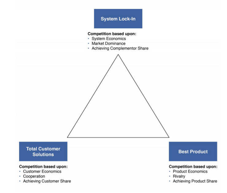
The “Lock-in” approach is based on a linkage between costumer and supplier. This means that by using the product, the customer can not easily go to another company for services or similar products. Although this is a good way to guarantee regular income and a long term relation with the customer it might tend to create a disapproval and customers will not buy the product in the first place. Therefore to achieve our goals we want to use the “Best Product” strategy, or rather the “Total Costumer Solution”. This approach is based on looking for a deep understanding of the costumer which allows us to develop customised value propositions for each one. This will create a link and long lasting bonding.
4.7 Adapted Marketing-Mix
In this subchapter we are going to define how we are going to approach our target market and attract the customer for our product. The previous stages that we described are for this decisions, in terms of the marketing mix, essential in order to invest your time and money in the most profitable way and ensure efficiency. What we did so far is displayed in the following Figure 96. It mainly pictures the process we did so far in order to find out about the target market.
Figure 96 displays the process from analysing the macro environment up to our target market and the meaning of marketing mix. The source is the presentation of the marketing class at ISEP Spring 2015.

After analysing the external environment, we focused on the potential customers and competitors in the market. Then we proceeded with our SWOT analysis and did the segmentation and positioning in the market. To understand now what the target of the marketing mix is, we can state that we need to understand the consumer behaviour and trigger his desire to buy our product. Doing so, we define our product and services with the concept of the „4P´s“ which are: product, place, price and promotion. These criteria are meant to create a relation between our company and the customer. It is a stimuli that will result in a response by the customer.
Figure 97

This concept is often used to explain the process of our action and the reaction of the customer. Apart from the stimuli of the „4P´s“ we also have situational factors like demographics, economic, situational, social and lifestyle that are affecting their decisional process.
Now we want to define what the meaning of each element of the „4P´s“ is and how we want to strategically use these aspect to attract potential buyers.
Figure 98 displays the dimensions of the marketing mix and a brief description of there meaning.

4.7.1 Product
To start off we already mentioned in terms of the product its various dimensions which are the core product, the extended product and augmented product. This is essential to fully understand the functioning of this criteria of marketing mix. As a definition „a product is a bundle of features, that targets the creation of customer value.“ [Harley Krohmer Christian Homburg, 2009]
To create this overall product value, we can systemise the lifecycle stage of the product in order to decide on the policy we apply to. There are the possibilities of innovation management, the management of products that already exist in the market and the management of brand names. As our product does not exist in its specific purpose in the market and it will implement the customer perception of novelty, we will focus our product strategy on innovation management and brand management. This includes gathering ideas, defining the concept, evaluating the concept and finally launching the market. The process of the innovation management starts with the firm establishment of your innovation. We did this in our chapter “2. State of the Art”, where we investigated on the functioning of the boat and also the technology we will apply. Ongoing we defined and selected the best concept for our boat with its design, measurement and engineering blueprint. Lastly the ultimate process stage will be the market implementation.
Our product strategy will be to offer high quality that we want to outline in our promotion and a extensive customer service that ensures a close and longterm relation with them. The product will have a long expected life time and throughout this we need to keep the customer linked to us in order to not only attain income by selling our product but also to offer maintenance services. Additionally there will be a three years warranty given on all components for their proper functioning. This will benefit our customer lifetime value, as already explained in the beginning of this chapter. In terms of our brand name, we created a unique and simple logo that is outlining the robust functioning of our product and the reliability. With this we want to create a certain emotion and recognition in the minds of the customer.
Figure 99 pictures our simple and unique logo.

The main dimension when thinking of this brand management, that we answered is: Figure 100

Our slogan will be: Autonomous Sailing, Always one step ahead!
4.7.2 Price
Now we want to describe the marketing mix in terms of the pricing of the product. The price of the product has some characteristics that are very important to mention. First character of the price is, that it can be change very fast. Contrary it is hard to return to former price levels in the same speed. One of the reasons is the high influence of the price towards the impression of the customer. Furthermore any change in the price can have a fast effect on sales and on the market situation.
Taking this into consideration, there are many factors that effect the price of the product and our strategy in the first place. Undoubtedly our product will be produced with the strategy of “engineer to order”. This means that as soon as a customer decides to buy our product we will start to build the boat with the necessary sensors or cameras that the customer needs. However the design of the boat will remain the same, which will decrease the total engineering costs, there are multifunctional applications for the boat, which will increase our overall organisational costs. As a result of our pricing strategy, the price has be adequate to cover our production costs plus a profit margin. While offering a product at higher prices, we will ensure a feeling of individualism, due to our production strategy, in the customers mind. Next the price also depends on the marketing objectives that we set before entering our segment. Due to a low competition and the fact that we offer a new innovative product, which has to be manifested by the quality we promised, our objective will be the product quality leadership. Higher prices have to cover the costs of our qualified employees and the costs for R&D. Nevertheless the still ongoing crisis in Europe and especially in Portugal are effecting our price concept as well. Although the outbreak of the financial crisis is already a couple of years ago, we are still facing the consequences, which are inherent for our price level. This might enable us to offer financing possibilities to our potential customers in order to skip the high purchase costs and split them over the years of usage. Besides this will enhance the bonding towards our company as well. To find the best price and still cover costs we will undertake a cost based analysis before entering the market. This will ensure that we can exactly define the overall production costs and then add a profit margin that is on the one hand acceptable for the customer and on the other hand will ensure a constant business growth. The overall strategy will be a so called “skimming strategy“ where we implement the product in the market to a reasonable high price to exploit the willingness of the customers to pay for this innovative boat. At the end this will allow us to quickly equalise our costs for R&D, product development and starting up the business. The other strategy would be a “penetration strategy” this strategy implements a relatively low price to get a rapid gain of market shares.
| Component | Cost |
|---|---|
| Sail | approx. 1500€ |
| Sensors & Camera | Dependent on customer |
| Hull | approx. 800€ |
| Keel | approx. 150 € |
| Rudder | approx. 100€ |
4.7.3 Promotion
The next part of the marketing mix is the promotion strategy. Basically the promotion is about transferring a statement towards the customer to create a certain knowledge, expectancy and desire to buy our product. The most common methodology to define this process is „AIDA“. This approach is about four main steps: Attention, Interest, Desire and Action. These are the four phases that a customer has to go through to finally purchase the product. The Attention part of the promotion channel used should implement an awareness of the product in the potential customers mind. The customer has to know that this product exists. Next Interest means that our promotion is provoking a certain emotion and persuading the audience of the need to purchase that specific product. After this the Desire part tries to implement a desire to possess the product and finally takes Action to buy it. Additionally to this we can state that in the modern marketing theory we see a growing impact of the fact of satisfaction. Marketing theory nowadays is also focusing on long term relationships and customer life time value which are the basis for sustainable business success. To enhance this, there are different ways for marketing communication explained in Figure 101. The source is the presentation of the marketing class at ISEP Spring 2015.
Figure 101

As our product is innovative, has a certain complexity and needs to be sold B2B, we will focus on a direct contact towards our customers. For us it will be important to design our way of advertising informative and comparative. As our product is not a totally new technology, we will try to persuade our potential customers by showing the additional value and benefits of our product. A good tool that we will use in terms of public relations will be a website, that we designed to inform potential customers about the product/company. This is an easy and cheap way that is nearly for everybody accessible. Nowadays the medium of the world wide web becomes more important in terms of advertisement. We also want to place our own business pages in social medias. The costs for a website to maintain are very low. There are many tools that will support us by designing the website on our own and maintain them. The biggest advantage for us is that we can more or less control our advertisement success with the supervision of the number of visitors on the website. Also we can use multimedia like videos or clips to demonstrate our product in action.
Although personal selling is one of the most expensive ways for promotion, we will use this as a core approach to reach customer interest. On the one hand we want to participate in different events like shows and expositions. This will help to be able to catch the customers interest by showing videos, demonstrations or persuade them face to face. Although there might be the risk that not everyone on this expositions will be interested in our product, this can be reduced by the topic of the expositions. There is also the possibility for the direct contact to use specialised leaflets like the one we already designed. It is possible to send them to potential customers or hand them directly to the customer by the personal seller.
We also want to use print media, which has the big advantages of the exact timing and you can do it in a short period of time. Although you might have the problem of a high percentage of dispersion you actually need to get a first idea of the product in the market. You could place advertisements in journals for robotics, engineering or researches like „Geo Magazine“ where you have at least a reader that is interested in technologies.
| Medium | Advantages | Disadvantages |
|---|---|---|
| TV | High availability, high usage in daily life | Difficult to reach only target group,declining acceptance of TV advertisement at high costs |
| Print media | Exact timing, short term predictability | High divergence loss, unspecific in terms of target group |
| Radio | Possible to regional segmentation, low cost, high reach | Missing visibility, missing attention |
| Outdoor Advertisement | Reaching young and mobile customers, precise placement of advertisement | Short period of attention |
| Internet/Online | Personalisation, interactive, multimedia, dynamic, up-to-date, control of advertisement success, reaches lots of jung target groups, usage of own homepage for communication purposes, usage for viral marketing | It will not reach all target groups, enhanced reactance |
| Direct Marketing | Personalisation, control of advertisement success, possibility to explain and focus on questions of the customer | Enhanced reactance |
| Sponsoring | Regional specialization, target groups can be addressed, image transfer | Short period of attention |
4.7.4 Place
Lastly we come to the place in the methodology of the „4P´s“. First there are three central decisions to do respective the market orientated activities.
Figure 102

The design of the distribution refers to our sales organisation and also to the ways of distribution we choose. There are basically two approaches, the direct and the indirect distribution. Indirect refers to the situation that an external distribution partner is in charge for a big acquisition function in the process. The following table is pointing out the pros and cons for these approaches:
| Distribution Channel | Advantages | Disadvantages |
|---|---|---|
| Direct | Direct control of the distribution events, direct communication with end customer | No possibility of mass distribution, high effort in your distribution organization |
| Indirect | Mass distribution is possible, costs for distribution shifts to intermediary, fulfill newest technology standards | No direct influence on sales, harder to communicate directly with end customer, problems with different interest between company and distribution partner, manufacturer relies on the competences of the distribution partner |
For the sales department we want use direct distribution and install a key account manager who will be responsible for maintaining a close contact with our customers and ensure a high level of satisfaction with our product and services. Furthermore we will offer trainings to guarantee that our sales employees are well prepared to convince potential customers about our product. For us it is more useful to have a low amount of highly qualified employees rather than a high amount of employees without the right skills to persuade customers. Personal selling demands a high level of qualification, starting with the understanding how to approach customers and then how to guide them on the right way to finally purchase the product. Also they have to understand the product which is more complex than others. In terms of the different distribution channels we choose to do indirect distribution through external delivery services. The main considerations that we took into account are to think about efficiency and effectiveness. Due to the fact that our company will be small and has a low limited budget, we can not afford to have an own delivery service and also we do not have any experiences. By negotiating a contract with an external delivery service, which can be DHL, Hermes, UPS etc., we can first guarantee a high level of know how in handling the boat and also we ensure safe delivery. The big disadvantage is that we will rely on the high standard of service by the external but to minimise this we can compare them and define common goals. Nevertheless we will have a direct contact to the customer.
Through the channel of direct distribution we will use fairs or directly contact our potential customers. Although this is an expensive way we will be able to build up an intensive relation with them and also adjust the functionality of the boat for each customer individually. The direct contact can be done by sales professionals at the customers ground or telephone, sending flyer and information material.
Additionally we have the design of our sales processes which includes the logistics. Our business will not have an extra storage for finished goods as we will engineer to order. This will decrease our costs. Furthermore we will offer the possibility to transport our product via container vessels internationally. For this we will design a transport box to ensure safety and a fully functioning product. Another possibility is to use trucks from our external delivery service. For this our transport box will be also very handy. Here is a list of possible transport modes and there pros and cons. [Philip Kotler, 2010]
Figure 103

Lastly summing up the chapter of marketing mix, we want to point out once again our goal to remain a close contact towards our customers in all stages of the sales process and the increased recognition of the customer lifetime value. In the relation to the marketing mix it refers to the Customer Relationship Management which is described in the following Figure.
Figure 104 displays the Customer Relationship Management. In red you see what we want to implement.

4.8 Budget
The purpose of this section is to quantify and choose how to spent an initial budget of 5000 Euro for the first year. At the moment we are not going to have any cost for employers and staff. The most important aim in the first year is to advertise and make known the product, for this reason lot of money will be spent in travels, to take our product in any of most important naval and robotic Fairs.
Figure 105 displays how we are going to spend the marketing budget.
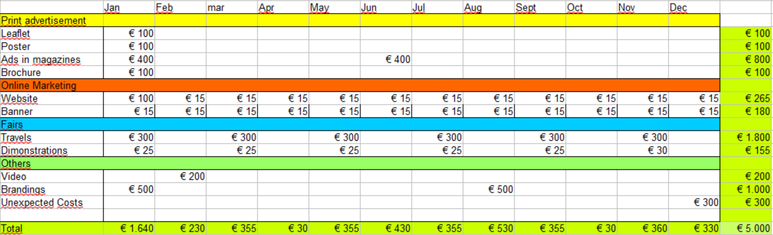
This is a list of Fairs in which we want to partecipate.
| Name | Topic | Location | Period |
|---|---|---|---|
| SMM | Leading international maritime trade fair | Hamburg | September 2016 |
| Salone Nautico | Companies of the maritime segment show their new innovations | Genova | October 2015 |
| Hannover Messe | The worldwide most important industrial fair, expositors show their new inventions and trends | Hannover | April 2016 |
| Autonomous Unmanned Systems & Robotics Expo | Exhibition of manufacturers, integrators and subcontractors, all presenting advanced operational capabilities | Israel | September 2015 |
| International Port Security | New innovations for port security | London | June 2015 |
| AUVSI’s Unmanned Systems | Largest global community of commercial and defense leaders in intelligent robotics, drones and unmanned systems | New Orleans USA | May 2016 |
4.9 Strategy Control
The strategy control is a tool for us to make sure that we are on the previously defined track and still attaining our marketing goals. To ensure this we will monitor, compare and correct our work performance. We need to ensure that our activities are done in a way to enhance the accomplishment of our organizational or marketing goals. As we set our objectives and analyzed our market opportunities we have to monitor our achievement. Doing so we need to get data from our performance which can be customer feedback or quantifiable data like our return on investment, liquidity development or market share. All of these data has to be collected regularly and analyzed by our employees. If there are some asymmetries occurring we need to take action and get back on track. A well implemented controlling will build a basis to let us know if we attain our goals or not, it will be empowering for our employees as a platform for a feedback on their performance and also will protect the workplace. Our basic control process will be divided in three steps. First after defining our goals and standards we will measure our actual performance, then we will compare our performance with our goals and then you can take managerial action. The goals set by us now can be either to easy to attain, which is not challenging and therefore should be increased or they are too high so we need to adjust them or find new strategies to attain these goals.
Figure 106 displays our process of controlling the marketing and organizational activities.

To measure our performance there are different possibilities. First there is the personal observation. This has the advantages that you get firsthand knowledge and also the information retained is not filtered. On the other hand it is very time consuming and may be more costly than other possibilities. Next there is the statistical report. This is an easy way to visualize you performance and also effective in showing the relationships involved. Oral reports are one of the fastest ways to get information and also allow verbal and nonverbal feedback. We want to use this as we are going to ask our customers if the product matches their expectations and if they are satisfied with our customer service. Lastly there is the possibility of written reports. This will enable us to store and retrieve the knowledge gathered.
Our whole process of control in respect to our managerial decisions will look like the following: Figure 107

This principe of measuring our marketing efficiency will be a process that can be also applicable for other areas such as our financial area, human resources and production area to monitor our productivity and efficiency.
To support this process we will implement a management information system (MIS) which will provide our management with needed information on a regular basis.
4.10 Conclusion
Summing up the previous chapter, we can state that our innovative product will attain a unique selling position. We do not have direct competitors that offer similar range of functioning. To attain a high level of customer satisfaction we want to sell highest quality and retain a close relation towards them. For a long term profitability we want to offer a broad range of customer service and implement the feeling of uniqueness for each customer. We will focus on the B2B market by mainly approaching them in direct contact. Although personal selling is one of the most expensive and timely option, we consider it as the most efficient for our innovative product. For our first step in the market we will use leaflets and articles as promotion and also focus on fairs to get a wide basis of potential customers to know about our product.
By end 2016 we want to explore the european market and increase our profitability by improving our production processes and marketing strategy. This will be done by our extended level of experience from our primary market Portugal. Our core standards of our company will be high quality, fair customer and employee treatment and offering best service at the market.
Figure 108 displays our competitive advantages that will enable us to create a unique position in the market and in the customer perception.

Figure 109 is the visualization of our plan for the upcoming years.

5 Eco-eficiency Measures for Sustainability
5.1 Introduction
Sustainability is currently playing a major role in all our lives and the issue is causing much debate over the planet to save our civilisation and environment. It has been on the forefront of the international agenda for more than a quarter of a century, yet we continue as a species to build economies at considerable costs to the environment. It is evident that social and economic sustainability are only solution although to do so we must have a healthy plan.
“These are the living forms that constitute the fabric of the ecosystems which sustain life on earth – and the barometer of what we are doing to our own planet, our only home. We ignore their decline at our peril.” Marco Lambertini Director General WWF International[WWF, 2014]
The world ecosystem is being undermined by the human race, as we have become the dominant force that shapes these systems for our own gain. It appears that the solution is a healthier balance to preserve our plant, from supporting the quality of life for animals and humans in their communities around the globe. The diagram below illustrates the three most in important domains that affect our way of living.
Figure 110

- Environmental
- Social
- Economic
These interconnected variables are linked indefinitely to achieve eco-efficiency, and each variable has an array of sections that must be achieved to conquer the sustainability of our planet.
Our company, “Horizon Sail” thrives to become sustainable by seizing all opportunities to do so at minimal risk to the business, people and the planet. The environmentally friendly approach to material selection and sourcing combined with our aware manufacturing process and efficient distribution is a priority.
Our business plan is to be an accomplished manufacturer and distributor of autonomous sailboats for a variety of environmental aids (sea exploration data etc.) situated in Porto, Portugal. The focus to target Europe was made because of their green policy advancements in recent years. As our analysis in the Marketing chapter has shown, there is a large gap in the market for data collectors at sea. In 2015 we strive to open our first manufacturing site and distribution warehouse. Our products are custom made for the clients and from an array of easily resourced materials that are supplied from companies in Portugal.
| Connection | Goal |
|---|---|
| Customers | World wide environmental aid workers/ Researchers/ Security etc. |
| Suppliers | Local suppliers to develop safe relationships to ensure quality in deliveries and materials for client deadlines. |
| Stakeholders | The stakeholders need accurate, relevant and reliable information regarding investments and targets for our market. |
| Employees | Major asset, dedication and skill is required for a sustainable vision of the company. |
| Communities | By operating environmentally friendly and being committed in the local community we will try to build up a close relation. |
5.2 Environmental
We follow environmentally conscious design and manufacturing. Our key to the solution of environmental problems lies in our policy of adopting environmentally friendly products and production operations – the concept of a eco-factory. In the following we display the guidelines for an environmentally conscious product design that we want to apply on our product. In the end our target is to make our daily operations environmentally friendly:
5.2.1 Process
(1) To save energy and use renewable energy for our production. Using Energy Star approved equipment is a great way to reduce your total power consumption. The Energy Star sticker ist present on energy-efficient office equipment and home appliances.
(2) Minimising the number of components and ensuring minimal handling of components by Design for Assembly (DfA). DfA is a process by which products are designed with ease of assembly in mind. If a product contains fewer parts it will take less time to assemble, thereby reducing assembly costs. Design for Disassembly (DfD) methodology must be implemented to speed the disposal process. Deciding this method of disassembly during the early design phase and promoting it will allow for parts to be recycled easier at the end of the product life.
(3) To become a paperless business. Memos, manuals, and other documents do not need to be printed out. By taking your workplace communications to the email inbox, you can reduce your environmental impact while simultaneously saving electricity.
(4) To embrace natural lighting. Artificial light is expensive, unhealthy and environmentally unfriendly. Installing a day lighting system in your building does not need to be expensive. In fact, when you look at the long-term savings, it is actually a very cost-effective choice.
5.2.2 Pollution Control
5.2.2.1 Plant Emission
(1) Following environmentally conscious manufacturing by adopting environmentally responsible activities like “Zero Avoidable Pollution” and “Green Manufacturing”. Viewing and analysing waste, to transform it from an unavoidable result of our processes into a measure of our efficiency. The more waste a process generates, the less efficient it is.
(2) Selecting materials for the product design that is recyclable. Our idea is to select materials that have the right properties for our design and also can be reused and recycled at the lowest costs. Efficiency rise in energy uses and reduce the proportion of VOC (Volatile Organic Compounds) emission. Our purpose is to reach the “Gold Standard”.
- The Gold Standard, supported by WWF, is the most rigorous certification standard globally for carbon offset projects. It ensures that energy efficiency and renewable energy projects actually reduce carbon dioxide emissions and provide benefits to the local population.
(3) Our plant can use a cogeneration system to heat and power the factory. The heat can be used to raise steam for industrial processes or hot water for local heating, depending on the temperature. This simultaneous production of heat and power is known as “Combined Heat and Power” (CHP).
(4) Reducing the use of water. We want to use tools developed by the World Business Council for Sustainable Development and World Resources Institute to identify levels of water stress at each of our manufacturing sites. We want to use cooling towers with an efficient closed regeneration loop.
(5) Carbon Capture and Storage. This process can be used once we have a big fabric where we produce more than one sail at the time. As our aim is to reduce emissions of (CO2) as much as possible. A good technology to do is Carbon Capture and Storage (CCS). It is divided in three stages: Capture, transport and the storage.
- Post-process capture. (CO2) gets separated by a mixture of gases at the end of the production process, for instance from combustion flue gases.
- Transport of (CO2) in pipelines is a well known and mature technology. There is a significant experience in its transport for example in the United States with a network of (CO2) pipelines more than 6 000 km long.
- Geological storage of (CO2) involves the injection of (CO2) into appropriate geologic formations that are typically located between one and three kilometres under the ground.
By now there are still risks related to the possibility offered by the technology of (CO2) confinement that are mainly of two types :
- The unexpected release of massive amounts of (CO2) as a result of geological events or other modifications of the containment structures.
- And/or a gradual and silent leaking into the atmosphere prolonged in time.
Lastly we can state that today only five companies world wide use CCS. Some of the reasons for this are already mentioned previously and even in the upcoming years this approach of CCS will still be in a development phase. In the case that the process of CCS will be further developed and the risks minimised, we will use it for our production as well.[International Energy Agency – IEA, 2013]
5.2.2.2 Sea Emissions
In this section we want to consider and explain some of the most relevant problems related to oceans and seas environment and their causes. For our product we have to take in considerations these problems and understand how our product could be ocean-friendly with some considerations and raccomendations.
Sea Surface Temperature
Ocean surface temperatures increased over the 20th century. Even with some year-to-year change, the overall increase is evident, and sea surface temperatures have been higher during the last thirty years than at any other time since faithful observations began in the late 1800s. Global warming caused by emissions of heat-trapping carbon dioxide has increased the average ocean global temperature by about 0.1°C. This warming has occurred from the surface to a depth of about 700 meters, where most marine life thrives. [105] The only way to reduce ocean temperatures is to dramatically reduce emissions of carbon dioxide. However, even if we immediately dropped carbon dioxide emissions to zero, the gases we have already released would take decades or longer to dissipate.
Sea Level
The sea level has increased at an average rate of roughly 1,52 cm per decade since 1880. In recent years however the rates are increasing. Although changes in sea level is relative and vary by region, there is no doubt about the rise of the sea level. Along the U.S. coastline for example, sea level has risen the most along the mid-atlantic coast and parts of the Gulf coast, where some stations registered increases of more than 20 cm between 1960 and 2013. On the other hand the sea level has decreased relative to the land in parts of Alaska and the Northwest. Our boat can help to control these increase in the sea level.
Ocean Acidity
The ocean has become more acidic over the past few centuries because of increased levels of atmospheric carbon dioxide, which dissolves in the water. Higher acidity affects the balance of minerals in the water, which can make it more difficult for certain marine animals to build their skeletons and shells.
Over Fishing
The practice of commercial and non-commercial fishing which consumes fisheries by catching so many adult fish that not enough survive to replenish the population is abounding all around the world. Overfishing exceeds the carrying capacity of a fishery. On a global scale we have enough fishing capacity to cover at least four earth like planets. [106]
In relation to our product we will reduce our own carbon dioxide emission when producing the boat and also by the boat operating without relying on fuel. Another aspect is that our boat will be useful to monitor these environmental developments of the sea to get a better understanding and improve our precautions. The environmental impact of our product is really different from motorboats and reconnaissance drones that could be used for similar purpose. Using just renewable energy our boat doesn't produce (CO2).
These are some reccomendations for our boat end consumers:
- WAX Boat: A good coat of wax on a fibreglass hull prevents surface dirt from becoming engrained. This will reduce the need for detergents when you wash your boat. Pollen, dust, spores, or salt occur naturally and will do no harm when they are washed into the water. Also to wash topsides only and limit dock side hull cleaning to the above water surface area only will be an approach. Use a sponge to effectively remove light growth without creating the clouds of heavy metals usually caused by scrubbing. You can also rinse your boat with fresh water and use non-toxic cleaners. Many cleaning products contain phosphates and other chemicals that are toxic to aquatic ecosystems. Before using products with hazardous warning labels, such as skull and crossbones, try a natural cleaner like vinegar.
- Do not use toxic Antifouling paint : Most antifouling bottom paints are destructive to marine life. The newest coatings are formulated to have a less toxic and less long-lasting effect. Silicon, teflon, and other “non-fouling” paints rely on a slick surface to inhibit growth rather than on toxic ingredients to kill growth.
- Dispose properly old paint. Paints, solvents and thinners have to be disposed at an appropriate household waste facility. Do not dispose of paint or chemical containers in regular dumpsters.
5.3 Economical
„Maintaining high and stable levels of economic growth is one of the key objectives of sustainable development. Abandoning economic growth is not an option. But sustainable development is more than just economic growth. The quality of growth matter as well as the quantity“. [Deborah Doane & Alex MacGillivray, 2001]
In terms of economical sustainability in total, we can say that it is more than just a sustainable increase of the GDP in the economy. It includes a wide range of indicators such as investment, interest rates, productivity, labour market and employment statistics. These indicators are supposed to tell us, and let us influence the happiness and sustainable growth of the society.[Deborah Doane & Alex MacGillivray, 2001]
It is important to see that sustainability is said to be the ability of the economic system to adapt to the natural environment. Therefore we have to focus on adopting our company as much as possible to the natural environment, which will also lead to an increased reputation in the society. By being a certified company in terms of sustainable production or by being active in environment protection activities, we can improve our “Public Relation Management”.
In terms of our product, we will build it with components from Portugal and also 100% manufacture it here. This will reduce the cost of transportation and also increase the employment rate as we are focused to employ Portuguese people. In our production we will try to reduce the usage of electricity and water involved to improve our “ecological footprint”. Most of our transportation for exporting will be done by truck or ship in transport boxes to minimise the space needed. Additionally all our components will be chosen in respect to high quality and long life time expectancy. For this we will compare all our possibilities and evaluate them upon the criteria of lifetime, recyclability, costs, maintenance effort and also upon the way of the component itself is produced in terms of its ecological effects.
Our aim is to improve our sustainable manufacturing practice, viewed as production methods and technologies that focus on economic development and environmental protection simultaneously. The development of sustainable manufacturing practice is seen in three different stages: product, process and system. At the product level, the aim is to use the “6r approach” (reduce, reuse, recycle, recover,redesign, remanufacture). At the process level we want to optimise our technological improvements, and at a system level to evolve from a organisational-based orientation to an entire supply chain orientation. A number of studies, performed in different countries with using various statistical methods and techniques, found that integration of social and environmental aspects into technical and organisational activities undertaken by firms would increase economic performance. For example focusing on energy efficiency, water conservation, waste reduction, and other resource efficient practices for improving the ecosystem life and reduce ecological impacts, we are able to increase operational efficiency in the way of cost savings, reduce production lead times, and improve quality and productivity as well as improve revenues or profitability. [Norsiah Hami, Mohd Razali Muhamad, Zuhriah Ebrahim, 2015]
5.4 Social
Social Sustainability is defined as “the ability of a community to develop processes and structures which not only meet the needs of its current members but also support the ability of future generations to maintain a healthy community.”[BusinessDictionary.com, 2015]
In this context we will try to operate in a way to satisfy the needs of our costumers while manufacturing the product respectively concerned about the nature and its reproductive capabilities. We need to ensure that the nature is preserved over a long period of time and the normative claims of social justice, human dignity and participation are fulfilled.[Erich Griessler Beate Littig, 2005]
5.4.1 Work Schemes
5.4.1.1 Evaluation
Social sustainability and its management have achieved a greater impact for maintaining good relations towards employees, customers and the society. For maintaining a fair and good relation towards our employees we want to implement an evaluation system. This will help us to quantify the amount of work an employee has done and fairly install a bonus and recognition evaluation. Promotion has to be made upon the contribution made towards achieving company goals. Many times it is rather a subjective decision not based on qualifications. The evaluation will be held once a month and consists of quickly answerable questions that can be marked by a scale from 1-10. Line managers with a lower span of control than 15 people should always make the evaluation. This will ensure a close contact towards the colleagues. The next higher management level will evaluate the line managers and so on.
Also in relation to the evaluation system and the fact to ensure fair promotion on basis of commitment, we want to install incentives. These incentives can be variable, from extra days off, up to money bonuses. On the other hand it is possible to reward with trainings and seminars to improve the qualifications and reduce at the same time the accidents due to higher qualified worker.
5.4.1.2 Health
We want to install a health care system in the company. Once or twice a week we want a doctor to come to our company and do health checks for our employees. This will be on an optional basis for them as a service by the company.
The work environment is a vital ethos for our company, as we want our employees to feel adequately safe in there position. Implementing continuous training seasons and refresher courses will see the accident rate in work lower to zero. In addition external auditors will evaluate our safety scheme to ensure all areas are covered and employee satisfaction is exceptionally high.
5.4.1.2 Family
Another approach will be to become a family friendly company. In terms of being family friendly we want to build up cooperation with kinder gardens and install flexible working shifts. If we can offer good kinder gardens for our employees, they will feel confident that their kids are well and in good surrounding. This will improve the identification with our company and increase the willingness to commit towards their work. Additionally it is today quiet often possible to pay a certain percentage of your monthly wage into a fund held by the company. When working for a long time at this company you get a pension payment back, which will increase the income when the employee retires. This is a great chance for employees to finance themselves for the time after working, respectively if the governmental security system is not able to finance the retirement of people anymore.
5.4.1.3 Additional
Next if our company will start to grow and strengthen its position in the market we want to try to support our employees in finding accommodations and subsidise local transport tickets. On the one hand it will be easier for our employees to life close to the company or use an environmentally friendlier way to get to work.
5.4.1.4 Auditing
Another approach of ensuring social sustainability in terms of the society aspect will be to participate in a European auditing scheme. One for example is called “Eco Management and Audit Scheme” (EMAS) and consists of the idea to voluntarily audit your own company by externals in terms of eco-efficient management. After the audit we will be a certified company that fulfils more than the obligations made by the government. By publishing our report about the organisational effects on the environment we will be transparent for the stakeholders and also be held officially responsible for the goals we prescribe upon. To guarantee that we will achieve these goals we will install an environmental officer that will supervise and correct the production when getting “off the track”. However, our company will strive to accomplish the ISO 14001 as well. The EMAS is more or less an additional commitment based on ISO 14001.
5.4.1.5 Education
On going to our social commitment we want to source our products locally and strengthen the local economy. Also there is the possibility to support the community by holding seminars and presentations at local universities. We can teach student about work experiences and send engineers to the universities to speak about naval engineering and design. This will also increase our reputation at the young professionals and improve the accessibility to get highly qualified students in our company, maybe also by internships.
5.5 Life Cycle Analysis
5.5.1 Extraction of Raw Materials
 Analysis and quantification of the main components for the boat will be reviewed thoroughly, highlighting which raw materials, energy and resources are used throughout the production and transportation processes. In our case we mainly will rely on the use of wood for the main structure of the boat, which is a renewable source of material. Any other material considerations will be under a great amount of scrutiny to verify the best possible selection for our project. All chosen Material can be seen in chapter 7.5.7 Materials List.
5.5.2 Design Process
 Initially a unique design of an autonomous sailboat is required, which will be manufactured by us with a minimum of environmental impact. With our process of designing the boat we will try to reduce the quantity of material and provide a boat with proper form and with some energy sources that will not affect the environment. All design processes are mainly done by computer software, which reduces the paper waste for changes and also enables us to see the model in 3D.
5.5.3 Manufacturing and Production

Manufacturing and production is the process of changing raw materials into the final product, but also all processes that are going on during the production like transport for example. Generally when producing you always have an input, which can be energy, water, labour or the mentioned materials. While using or processing this input you generate waste, scrap or emissions, that we want to reduce as much as possible. Our aim has to be to use as less energy as possible, think about the best ways of working with the materials for our product and limit our waste to a minimum. As already mentioned we will employ an environmental officer that will supervise the progress towards achieving our stated goals and also help to optimise these production processes.
5.5.4 Packaging and Distribution

The distribution plan for the product from our manufacturing warehouse to the final user is to minimise the transport and packaging emissions. We plan to produce the boat in a place near the sea and in the first years our only market will be in Portugal. Our idea is to design a transport box which will use less space on boats or trucks when transported and also support the safety of the boat. It is our goal to always find the best route in terms of cost, environment, time and safety for our distribution.
5.5.5 Customer Use and Maintenance

The product lifetime of the boat is dependant on the level of expertise from the user and the intensity of usage. Due to a variety of activities that the boat may fulfil we must analyse all possibilities that may occur. These activities include sailing, mooring and maintenance.
First of all the boat has to be designed to need as minimal maintenance as possible. One of our main goals is to provide an easily understandable user manual for our customers that will help to take care and repair their own boat themselves. This will reduce our service costs in the first place and can help to improve customer satisfaction, if it is easy to repair on their own. The user manual also includes suggestions on the optimal maintenance but our company will provide the possibility to maintain the boat as well. Furthermore we wrote in the Marketing chapter also about offering seminars to teach the customers about the correct usage of the product.
5.5.6 End of life

The end of life includes the disposal and recycling of the product. Once the user decides that the boat is of no need anymore or it is hardly damaged, we will offer the possibility to take care of the environmentally correct disposal.
If the owner chooses to recycle themselves, we will have in the user manual stated how to do it correctly. In any possibility it will be easy to build it down due to our method which is called DfD, Design for Disassembly. The deconstruction at our company leaves us even the possibility to reuse some parts of the product again.
5.6 Our Company Policy
Reviewing the statements made throughout this chapter of the report it is now our company policy to manage of its activities so as to ensure that the consumption of energy and natural resources is reduced to a practical minimum. Our company’s corporate mission is to provide:
- Advance our technologies & solutions
- The best possible facilities and highest level of customer service our tenants
- Help customers effectively
- Limit the environmental impact
- Maximum value to our shareholders
- A rewarding work environment to our employees
- Work together with relative companies for mutual benefit
In pursuit of this mission, our company will strive to achieve a world-class reputation for energy management. We are committed to a high performance portfolio that uses energy in the most efficient, cost-effective, and environmentally responsible manner possible.
Energy management will play a key role in our business. It will support our plan to maximize profitability, strengthen our competitive position, and provide tenants with the highest quality of services. Our efforts to reduce energy use and prevent pollution will also support our commitment to our employees, the environment, and the communities in which we are a part. Toward this end, the company shall work towards continuously improving energy performance. We will establish specific implementation plans and will have made significant achievements in this area within 5 years’ time. The objectives as related to this policy are the following:
Provide the best possible environment for occupants of our facilities, while simultaneously maximizing energy performance Reduce operating expenses and increase asset values by actively and responsibly managing energy consumption Demonstrate commitment to our community and leadership in the real estate industry, by reducing pollution associated with energy use.
Horizon Sails will endeavor to meet or exceed the following energy management targets in service to these objectives:
- Reduce energy consumption in existing buildings by 35% over a 5-year period
- Reduce energy intensity by 25% in existing buildings over a 5-year period
- Design and construct all new developments to achieve 40% energy savings over local building energy codes
- Reduce carbon emissions associated with energy consumption by 33% by 2018
- Earn and maintain the ENERGY STAR label for 55% of our portfolio, beginning in 2020 and reapplying for and maintaining the labels each year thereafter also, publicly disclose them as appropriate or requested
This policy shall apply to all properties, business units, employees, and contractors in services in relation to our company.
5.7 Conclusion
In conclusion to this chapter, Eco-eficiency Measures for Sustainability, our company will adopt an ethos to work towards targets and goals which will see us progress over time as a major sustainable players for our environment. Our products will be under constant scrutiny during the entire life time, conducting rigorous policies and commitments to the environments, consumers and shareholders.
All these elements position us as a prominent player in the global environmental transition: a corporate culture enabling the company to generate competitive advantage. To follow this path and grow our business in the medium and long term means the involvement of every manager, employee and partner, individually and collectively in a work management strategy. In the next chapter the ethical and deontological concerns of a business culture will be highlighted and advanced, allowing us to deliver a broad understanding of what is right and wrong on several platforms of ethics. In the next chapter we are going to analyse the best way to act ethically correct as a company and in our team.
6. Ethical and Deontological Concerns
6.1 Introduction
In this chapter, we are going to outline the importance of a strong ethical basis in our business. Our main object will be to explain our ethical concerns in terms of engineering ethics, sales and marketing ethics, academic ethics, environmental ethics and liability of our sailing boat. Whenever setting up a new business idea and entering the market, you are in many ways confronted with ethical questions regarding the ways you operate. Ethical questions arise already in the ideation phase of a new product where you deal with core questions regarding your materials and the functioning itself. All ongoing steps will have an impact on the environment and also on humans that are in direct contact with the production process or by using it. These various situation are characterized by multifaceted decisions which will lead in a wrong direction when not, in terms of ethics, are thought through. Furthermore they are hardly reversible and shape an image in the customer minds. As our ethical action will enhance trust and good relation with customers, suppliers and other businesses it is a core process for our effective development and strong positioning in the market.
6.2 Engineering Ethics
Whenever you are designing a new product and thinking about the functioning as well as its components you are obliged to think also about the effect on the environment and user of the product. Our civilization is based on engineering and its progress. New technologies enable us to be more efficient, faster but also may involve negative side effects on the environment and human health. In consequence it needs some rules or guidelines that apply to engineering processes. There are standards of good practice set and formulated in a “Engineering Code of Ethics“. We will apply this to our product by naming them and referring to our engineering approach.
(1) Hold paramount the safety, health, and welfare of the public. In order to ensure safety, health and welfare of the public, we will design a boat that will be safe to use for any customer and also not be a threat when fulfilling its missions offshore. We will use highest standard of technology to minimize the threat of an unnavigable boat. Furthermore we focused our material research on sustainable factors and also to care about the recycling at the end of its lifetime.
(2) Perform services only in areas of their competence. To due the fact that non of us has a profound background in naval engineering we try to keep in close contact with specialists from divers engineering fields. This will ensure a high level of competence and quality in performing the prototyping.
(3) Act for each employer or client as faithful agents or trustees. It is important for us to remain our good teamwork on this project in the future. Only by a free flow of information regarding the product we will create a successful working atmosphere. However, this free information flow will be useful to enhance a feeling of participation for the professionals in the company who will benefit from new ideas. The success of an innovative product lies in the commitment of every professional employee.
(4) Professionals within the company will conduct themselves honorably, responsibly, ethically, and lawfully so as to enhance the honor, reputation, and usefulness of the profession. This point is very important for us. Everybody in this team will do his best to fulfill these criteria. By doing so it will increase our reputation in the society and improve our brand name. [112]
6.3 Sales and Marketing Ethics
As the desire to make fast money is getting more and more important in our daily life, we see an alarming trend growing in business society. Many marketing and sales activities are based on these selfish and ruthless principles such as, focusing solely on the singularly most important sales activity to accelerate growth. Our company wants to instead be transparent and achieve a long term relation with our clients. Therefore we will be consistent in our marketing strategy and honest about our product. Additionally we will not use any advertisement strategies that includes to talk other competitor products down. This approach will enhance a profound image of the company, enlarge our authenticity and also the customer confidence. Furthermore we strive to manufacture a high quality product offered to fair prices. When doing advertisements our potential customer will get the information needed on the technology, functionality and the way of manufacturing it. This will provide him with a solid basis to decide himself if to purchase or not and if the product reaches his expectations. Issuing public statements is vital to perform the objective in a truthful manner. We want to only present our company and product in a fair manner. We have to ensure that we only state proven facts about the product that we can be held responsible for. Finally, instead of promising our customers some features and benefits of our product that can not be delivered we want to try to get an understatement.
6.4 Academic Ethics
Due to our various study backgrounds at have only a little relation to the topic of naval engineering, we highly relied on gathering knowledge from different sources. These sources can be books, articles or websites regarding the topic of boat design and construction. In these terms we are stating the source of these knowledges in the bibliography to determine who's property it is. As our report is the basis for our business idea, we will be transparent in our mission for every stakeholder. These report is free accessible for everybody. Furthermore we created a website to enable everybody to get information about us and the product. Our software used will be only based on free ware to avoid any licensing problems. Furthermore we are working in a group of people from different countries. This implies that we are used to different ways of working and have been raised surrounded by different cultures. Also we may have different aims and expectations of our goals regarding the project. Nevertheless we will try to work as a team by respecting the others and fulfilling each task at our best. Regarding the relation to our coordinators and teachers in class we will confront them with respect and work in class when asked to. Also we will prepare our meetings and homework for class.
6.5 Environmental Ethics
The point of environmental ethics concerns the fact of our ecological footprint. This means that every product has a certain impact on the environment and future generations living on this planet. Our mission is to minimize this ecological footprint in order to preserve the nature and manage to maintain a livable condition. The ethical approach should be to focus the design on reusable material and also think about the end of the lifecycle of the product. This means that our company wants to offer a recycling/ disassembly of the boat or components when not functioning anymore at our costs. To avoid that this is happening early in the life cycle we will only use high quality material and ensure that our product is as less harmful to the environment as possible.
The material selection process was intensive and time consuming to ensure the best quality of product for the customer. A vast array of possible materials were highly scrutinised for each component, and compared individually. The final selection process was deeply deliberated and cooporated fully with our companies ethos and ethical demands for the environment, shown above. The materials selected were proven to reduce the ecological footprint on the environment and communities in which the materials were resourced. As mentioned in the sustainability chapter we want to participate in the EMAS in order to operate environmentally friendly. This is an additional commitment apart from the regulations of the European Union and is based on the ISO 14000.
6.6 Liability
As a matter of fact the autonomous sailboat can also be a hazard for others when being out of control or capsizing. This may involve people or the ocean environment. Also we can be hold liable for the promised quality and warranty given. This is why we will exactly define the terms of our warranty and let it be checked by legislative authority. If there are any customer complaints occurring we need to find a reasonable way to satisfy both sides and remain our relationship in a respecting way. Furthermore we will enclose a user manual for our product to guide the customer along the functioning of the boat and also point out the hazards that are involved by using it. Next we have to maintain safety standards at our production, to protect our employees and also for ensuring safety when operating in sea. Some directives regarding our product are:
- Machine Directive (2006/42/CE 2006-05-17);
- Electrical Safety: Low Level Voltage Directive (2006/95/CE 2006-12-12);
- Restriction of Hazardous Substances (ROHS) in Electrical and Electronic Equipment Directive (2002/95/EC 2003-01-27);
- Mandatory adoption and use of the International System of Units (The NIST International Guide for the use of the International System of Units).
Additionally we need to be aware of copyrights, trademarks and patents and must not infringe these. Therefore we designed a logo ourselves and checked on the “wipe”, which is the abbreviation for World Intellectual Property Organization [World Property Organization, 2015] if the name “Horizon Sail“ is already used. As our product will be implemented in the market, we need to register this as a trademark including our logo.
Last but not least we will follow the legal framework provided by the EU and the local governments.
6.7 Conclusion
Summing up this chapter we see that there are various ethical dimensions that we need to take into consideration. On the engineering code of conduct aspect, we have implemented safe enviroments for our knowledgable associates, working in intensively researched areas while holding these employees to there actions in the work place. Secondly, the sales and marketing platform will perform honestly towards connections with the company, from suppliers to customers, holding our actions acccountable and operating to our statement in all advertisments. The academic ethical principles relies on our gathering of information which will always come from reliable sources which will be accounted for accordingly in the biliography. This also includes open-ware softwere and any other platforms which will be used in the development of the project. As the basis of our company we have implemented values for the interaction in the organisation itself and towards our environment. Adopting fully recycleable methods and astute intropective material choices to ensure a lower ecological footprint. Finally, the liability factor will adhere to standards developed internationally, from ISO and EU standards. We have included a warrenty policy for the product to assure customers confidence and recognition as a reliable company. The ethics is a vital sector for our project, which has been fully analysed to establish our companys ethos which was implemented by the group of highly focused and highly committed professionals.
7 Project Development
7.1 Introduction
In this chapter we are going to document our progress in the project of the autonomous sailboat. The autonomous sailboat is required to mainly be a data collector that can autonomously navigate and fulfil its mission in a prior defined region. We take the requirements and objectives defined by our client LSA into account when designing our boat. All our solutions for these approaches, we will sum up regarding the best ways to build the hull, sail, rudder, mast, etc. Additionally, we defined functional tests that we will do when finishing the prototype, all our results will be displayed here in this chapter.
7.2 Architecture
7.2.1 Initial Concept
Our first idea was to focus on the Paralympics 2.4 model, which is stable and almost unsinkable, we produced a 3D model to see how we could modify it for our goals. However we quickly realised that it was so far from what we needed. It did not incorporate the required rigid wing-sail, thus using a standard soft sail and rigging which is too cumbersome for our design. This model is designed for racing in predetermined waters and in a delimited short circuit and our boat has to be able to sail in every conditions for a long time, so we decided to rule out the idea. Figure 111 displays our first idea of a sailboat in a 3D Model.


7.2.2 Secondary Concept
The second concept on which the team considered all parameters of the design requirements. It was decided to focus on stability and precision when designing the hull, keel and rudder and experimentation when designing the rigid wing-sail. Our hull concept can be seen below, it has several features, which compliment the requirements of our boat.
Figure 112 shows the drawing for the sailboat regarding our requirements and objectives including the rigid sail.

7.2.2.1 Hull and Keel
The hull design was adopted from the variety of concepts that allow for the best possible design for our boat requirements, it was the teams decisions to use the lazer boat dimensions as a platform. The calculations in the following section will clarify these dimensions in accordance to the rigid-wing sail. The lazers boat will be purchased on the market, if we select another boat the success when combining both the sail and hull in the construction stage may differentiate.
Figure 113 demonstrates the blueprints taken from the 3D model regarding the Hull and Keel concepts.

The hull has design has been made to accommodate the stability requirements of the boat when in operation in unstable waters, the V hull design adds to this stability and control. Additionally the keel design is also there for the stability of the boat this is more advanced that considers the forces on the wing sail when selecting a depth for the keel. These calculations can be seen in the following section.
Figure 114 shows this SolidWorks 3D model of the hull in different perspectives.


The hull and keel design have been presented below on a Solidworks 3D model, extra advancements such as the deck and several other components must be added to this for the final body of the boat. At this time our concentration is lying in the design, construction and testing of the rigid wing sail.
Figure 115 is an ideation by SolidWorks of the hull and the keel.


7.2.2.2 Rigid Wing-Sail
After relying on our hull design to be taken from a lazer our concentration is now to develop a rigid wing sail, which can be accommodated by a boat of this size. The lazer dimensions can be seen in the table below. The rigid wing has a structurally stable design with limited but not zero flexibility, our concept is to build a secure internal structure using spaced ribs and a vertical structural member too this we will apply a light, thin and strong material which acts as the skin or sail area. This skin is the initial part of contact with the environment and therefore must be correctly designed and finished layer to protect it from the ocean environment.
Figure 116 Wing concept.

The form of the wing has been defined in order to concentrate the maximum forces of the wind at the first 1/3 area from the base inline with the mast. Therefore we can guarantee that it will support all the forces applied by the environment axial, torsional and bending moments. The increased inclination from the back of the wing has also reduced surface area and the top is shaped in this format to allow air contact of the wing while optimising the wind speed.
Figure 117 Centre of Pressure on Wing Geometry.

The flap has the responsibility in making the wing turn. To make it possible an actuator is allocated on one rib of the wing and connected to one rib of the flap. Both parts are fixed together by a piano hinge, which acts as a centre of rotation, turning the linear movement of the actuator into a rotation movement for the flap. In addition, the actuator will be configured to move itself a specific distance that gives 20º to the flap for each side.
Figure 118 Flap and Actuator.

Figure 119 shows the flap and actuator design method.

Figure 120 displays an actuator and flap close-up.

7.2.2.3 Ribs
The ribs are the structural skeletons of the wing-sail, thus great care must be taken when designing such an important component. Vast amounts of research has been produced for the aviation industry, this lead us to the NACA 0012. This airfoil design is symmetrical and reasonably easy to produce initially coordinates were plotted on basic graph paper and later transferred to an Excel sheet where the figures could be analysed before being transferred to a 2D Model. Below we can see the initial plotted diagram and the coordinates of the NACA 0012 airfoil.
Figure 121 Plotted NACA 0012 Airfoil.

Table 29 NACA 0012 Coordinates.

Once the coordinates had been validated they were transferred on to Solidworks software, here the ribs were modified to accommodate the mast and I-Beam structural supports. The ability to modify the profile of the ribs was also an option below it can be seen that large amounts of material have been removed from the rib, this does lower stability but it also lowers the weight of the sail. The reduction in weight should produce a greater lift and enhance our sails performance while maintaining the structural efficiency. The rib geometry has also has changed to straight alignments to ease the manufacturing process of the sail. The remaining rib designs can be seen in 7.3.3 Final Wing & Boat Design and under: blueprints2.pdf.
7.2.2.4 Stabiliser
The stabiliser has the same function as the flap. However, as it is smaller, we decided to use a different mechanism to make it move due to an actuator is really expensive and we do not need so much power for the stabiliser. Therefore, the stabiliser has been designed as a symmetrical part with an axis in the centre connecting the static part and the movable part. Then, a servomotor will be situated in the static part and connected to the movable part with two rigid cables that will transmit the rotation from the servo.
The stabiliser is fixed to the wing through a horizontal stainless steel tube with different holes to adapt it on the suitable position. Both tubes will be put together with two screws, one passed horizontally and the other vertically. It will support all strengths from different directions. The front part of the wing tube will has the same distribution of hols but we have not put anything. The idea is to make it adaptable so a counterbalance, a wind sensor or whatever the user wants can be put.
Figure 122 Beam Connection Bolts.

Figure 123 Servomotor Positioning.

7.2.2.5 Maintenance Design Facilities
To get access to the electronic devices there are some “doors” distributed along the wing that the user can take out easily with the screws. They are distributed on the next way:

The figure above indicates the 124 window locations for the following devices, these will allow access for the user to upgrade, repair and maintain desired appliances. The window for each appliance is as follows:
- Battery
- Actuator
- Junction Point
- Navigation Light
- Servomotor
Figure 125 Sealing the Window.

7.2.3 Final Wing and Boat Design
The final combination of both the hull, keel and wing concept has been a rigorous and time consuming portion of our project development since innovative and abstract designs have been fabricated out of competitors and a vast area of design concepts. Initially, the wing-sail skeleton and final product will look like the following,
Figure 126 Rigid Wing Sail Skeleton.

Figure 127 Rigid Wing Sail.

The final wing-sail has been designed by following theoretical laws of physics and now we must combine this sail to the proposed hull body of the Lazer boat. The final products connection for this can be found in section 7.8.1 Mast Rotation in the functionalities chapter. The hull and keel body have also been calculated in the next chapter to accommodate each other full regarding materials choice and dimensions of the boat.
Figure 128 Final Sailboat.
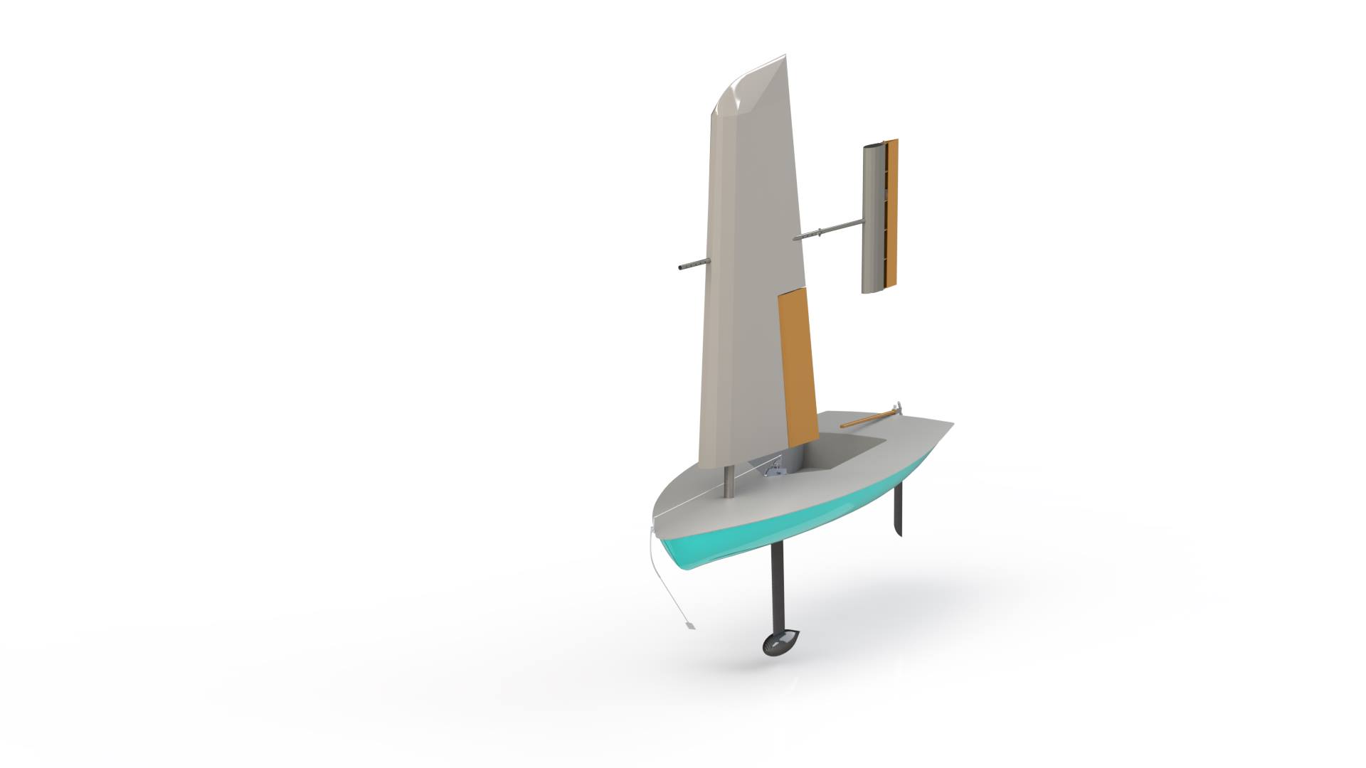
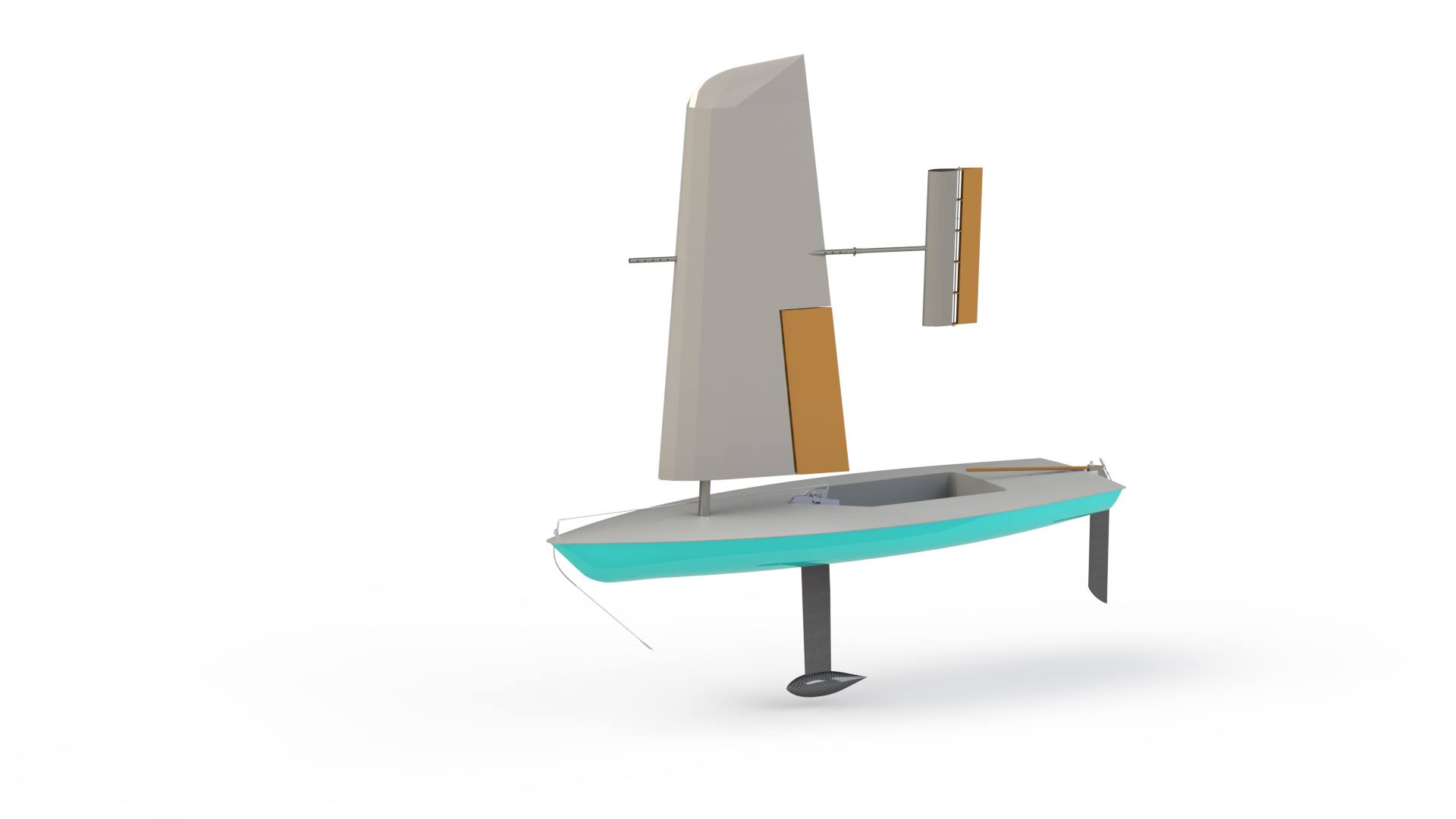
The remaining blueprints can be seen in the following PDF, blueprints2.pdf. This link indicates all dimensions required to manufacture the wing to a great deal of accuracy. The blueprints indicate sizes for the following components,
- Wing Rib 1-8
- Flap Rib x4
- Stainless Steel Mast
- Wooden Mast
- Wooden Union 1/2
- Horizontal Stainless Steel Member/Connector
- Jib Rib x6
- Stabiliser Mast
- Stabiliser Tube Connection
- Static Stabiliser Rib
- Extra Plans
- Wing Ribs Distribution
- Stabiliser Ribs Distribution
- Rib and Flap Positioning
- Material Numeration List
Please address the PDF file for the following information.
7.2.4 Electronic Architecture
It is paramount that the configuration of electrical appliances is predetermined due to our proposed manufacturing process. The system will be enclosed in the skin of the wing this causes great difficulty to renovate the system within the sail. The prospected components and locations at which the will be inserted to the wing are as follows:
- Battery ⇒ Position: Base Rib
- Navigating Lights ⇒ Position: Peak of Rigid-wing sail
- Actuator ⇒ Position: Central Beam of the Flap offers most control.
- Wind Sensor ⇒ Position: Front Facing Beam
- Servo Motor ⇒ Position: Central Rib of the Stabiliser
Figure 129 shows a schematic drawing of our wings electronic system.

This electrical design will let us test the system under certain conditions and ensure our design can accommodate these electronic appliances in terms of positioning and connections. The black box stated in the schematic diagram above is delivered by the autonomous experts at LSA, this will be connected to the hull and deliver commands by acting as the control unit of our sailboat. The connection via these appliances will be Wi-Fi or Bluetooth, which ever the client prefers.
7.3 Calculations
The calculations cover all sections stated in the state of the art, these are as follows, Buoyancy, Dynamic Stability, Velocity of the Wind and Centre of Gravity. These calculations clarify the boats ability to operate correctly with the dimensions of the lazer hull, which can define the weight of the sail to achieve equilibrium in the boat.
7.4.1 Buyoancy
Figure 130 is a picture of our calculations on the hull design.
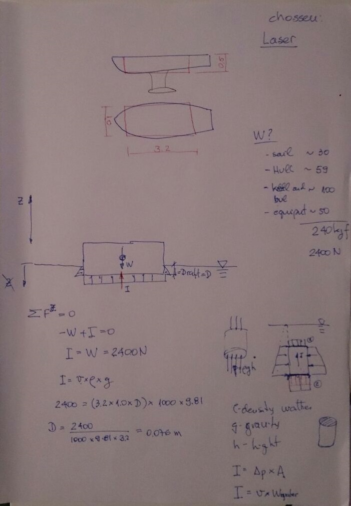
We assumed the hull as a rectangle to simplify calculations, and inserting basic measurements as length, height, beam and an approximate weight of 2400 kg for the boat, from this we could receive the Draft and the Impulse from further calculations.
7.4.2 Dynamic Stability
Figure 131 displays our calculations on the dynamic stability of the boat.
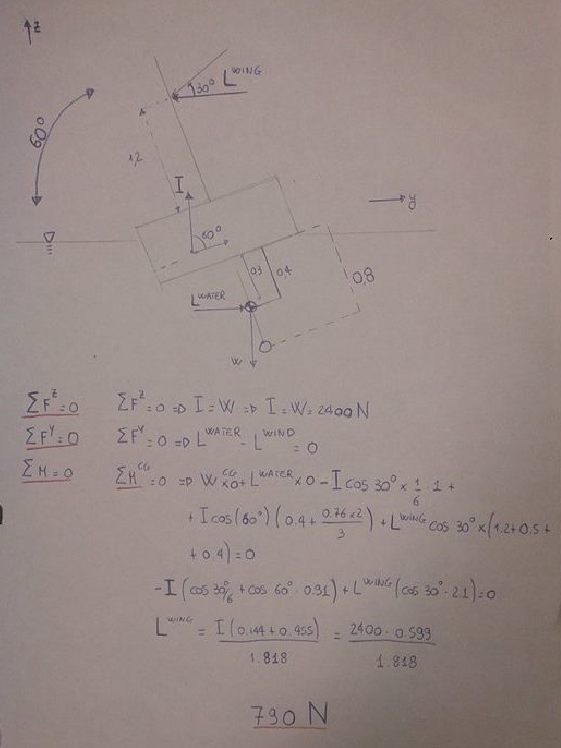
The calculation sheet above ensures stability of the boat where we have assumed a Centre of Gravity at at 0.4 metres from the base of the hull. We calculated the lift of the wing necessary to reach a resulting moment in the Centre of Gravity equal to zero. The value of lift is found to be 790 N.
7.4.3 Velocity of the Wind
Figure 132 is a picture of sail dimensions and the calculation about the possible wind velocity.
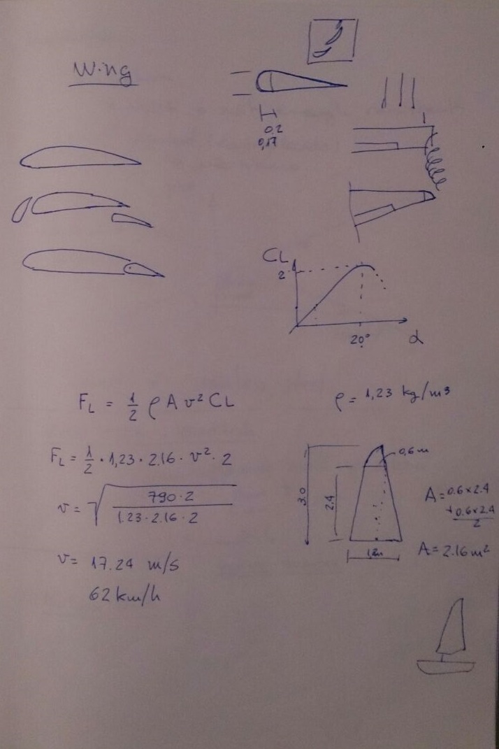
Now that the lift of the wing has been found we can use this to achieve the maximum wind speed the boat may operate under. This was found using the Lift Coefficient Equation.
7.4.4 Fixing Centre of Gravity
Figure 133 displays our calculation about the centre of gravity.
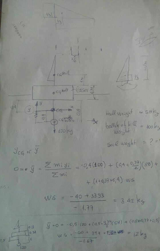
To reach a stable boat it is fundamental to have a low centre of gravity, fixed as said above at 0.4 metres from the bottom of the hull. We used this value to calculate the weight of the wing. It can be seen to be 3 kilograms that is not great enough to produce with our budget and materials available. The distance between the hull and keel and the keel weight has been increased to 1m and 120 kg, which improved the sail weight to 12kg. This value is viable and available for the process and materials we will later select in the project development.
7.4.5 Modifications and Conclusion
We modified some data from the initial model to reach a better results; we took height, beam, length and volume of Real Lazers to reach a more real result.
- Assuming a hull length of $4.208 m$ a hull height of $0.379 m $, a beam hull of $1.34 m%$ we reach a volume of $ 0.931 {m}^{3} $ and a rectangle volume of $5.927 {m}^{3} $
- Assuming a Sail weight of $16 kg$, hull weight of $59 kg$, keel and rudder of $100 kg $, and equipment weight of $50 kg$ we reach a total weight of $225 kg$.
Equation \ref{eq:totalweight} illustrates how to calculate total weight.
\begin{equation} Total Weight = Sail + Hull + Keel + Rudder + Equipment= 59 kg + 100 kg + 50 kg = 225 kg. \label{eq:totalweight} \end{equation}
- The Impulse is calculated in Equation \ref{eq:Impulse}.
\begin{equation} Impulse = Weight\times10= 225kg\times10 \frac{m}{{s}^{2}} = 2250 N \label{eq:Impulse} \end{equation}
- Assuming a Density of water of $1027 \frac{kg}{{m}^{3}}$, a gravity acceleration of $9.81 \frac{m}{{s}^{2}}$ we reach the Volume under water in Equation \ref{eq:VUW}
\begin{equation} VUW=\frac{Impulse}{Density\hspace{0.1cm}Water \times Gravity\hspace{0.1cm}Acceleration}=\frac{2250 N}{1027\frac{kg}{{m}^{3}}\times 9.81\frac{m}{{s}^{2}} }=0.223{m}^{3} \label{eq:VUW} \end{equation}
- To analyse the moments,we use the scheme of the Figure 119 about the dynamic stability.
The condition for the dynamic stability is given by Equation \ref{eq:dyn}
\begin{equation} \sum_{k=1}^N {M}^{CG}=0 \label{eq:dyn} \end{equation}
We assume an angle of attack of $60°$. The Weight moment is in Equation \ref{eq:wem}
\begin{equation} Weight \times Arm = Weight \times 0 = 0. \label{eq:wem} \end{equation}
The Lift water moment is given in Equation \ref{eq:Lift}
\begin{equation} Lift\hspace{0.1cm}Water \times arm = Lift\hspace{0.1cm}water \times 0 = 0 \label{eq:Lift} \end{equation}
- The Impulse moment is divided into two components; the first is given by Equation \ref{eq:I1}
\begin{equation} Impulse \times cos{(Angle\hspace{0.1cm} of\hspace{0.1cm} Attack)} \times Distance\hspace{0.1cm} between\hspace{0.1cm} Impulse\hspace{0.1cm} and\hspace{0.1cm} CG = 321.922 N\times m \label{eq:I1} \end{equation}
.
- The second is given by Equation \ref{eq:I2}
\begin{equation} Impulse \times sin{(Angle\hspace{0.1cm} of\hspace{0.1cm} Attack)} \times Distance\hspace{0.1cm} between\hspace{0.1cm} Impulse\hspace{0.1cm} and\hspace{0.1cm} CG = 485 N \times m \label{eq:I2} \end{equation}
.
After this we reach The lift wing moment using the \ref{eq:dyn} that is given by Equation \ref{eq:It}
\begin{equation} Lift\hspace{0.1cm}Wing\hspace{0.1cm}Moment= Impulse\hspace{0.1cm}Moment1+ Impulse\hspace{0.1cm}Moment2= 321.922 N\times m + 485.545 N\times m = 807.467 N\times m \label{eq:It} \end{equation}
.
- Assuming an height of the centre of gravity of $0.4 m $ and an height of the centre of pressure of the wing of $ 1.2 m $, we reach a Lift of the wing given by Equation \ref{eq:Lwi}
\begin{equation} Lift = \frac {Moment\hspace{0.1cm} Lift\hspace{0.1cm} Wing}{cos{30} \times (height\hspace{0,1cm} CG + Height\hspace{0.1cm} Center\hspace{0.1cm} Of\hspace{0.1cm} Pressure\hspace{0.1cm} Wing + Height\hspace{0.1cm} Hull)} = 471.066 N \label{eq:Lwi} \end{equation}
.
- Considering a Density of air of $1.23 \frac{kg}{{m}^{3}}$, a sail area of $2.4 {m}^{2}$, and a lift coefficent of $1.5$, we reach an air velocity given by Equation \ref{eq:AV}
\begin{equation} Air\hspace{0.1cm} Velocity =\sqrt{\frac{Lift\hspace{0.1cm} Wing \times 2}{Density\hspace{0.1cm} of\hspace{0.1cm} air \times Sail\hspace{0.1cm} area \times CL} } = 14.6549 \frac{m}{{s}^{2}} \label{eq:AV} \end{equation}
.
- Utilizing a Hull Height of $0.37 m$, a Hull weight of $59 kg$, a Bulb weight of $100 kg$, a Sail Height of $2.4 m$, a distance between bottom of the hull and CG of $0.4m$, a distance between the centre of the hull and CG of $0.585 m$, a distance between the keel and CG of $0.6 m$, and a distance between the sail and the CG of $1.57 m$ we obtain a Sail weight of $16.232 kg$.
Figure 134 shows the final model, with some modifications.
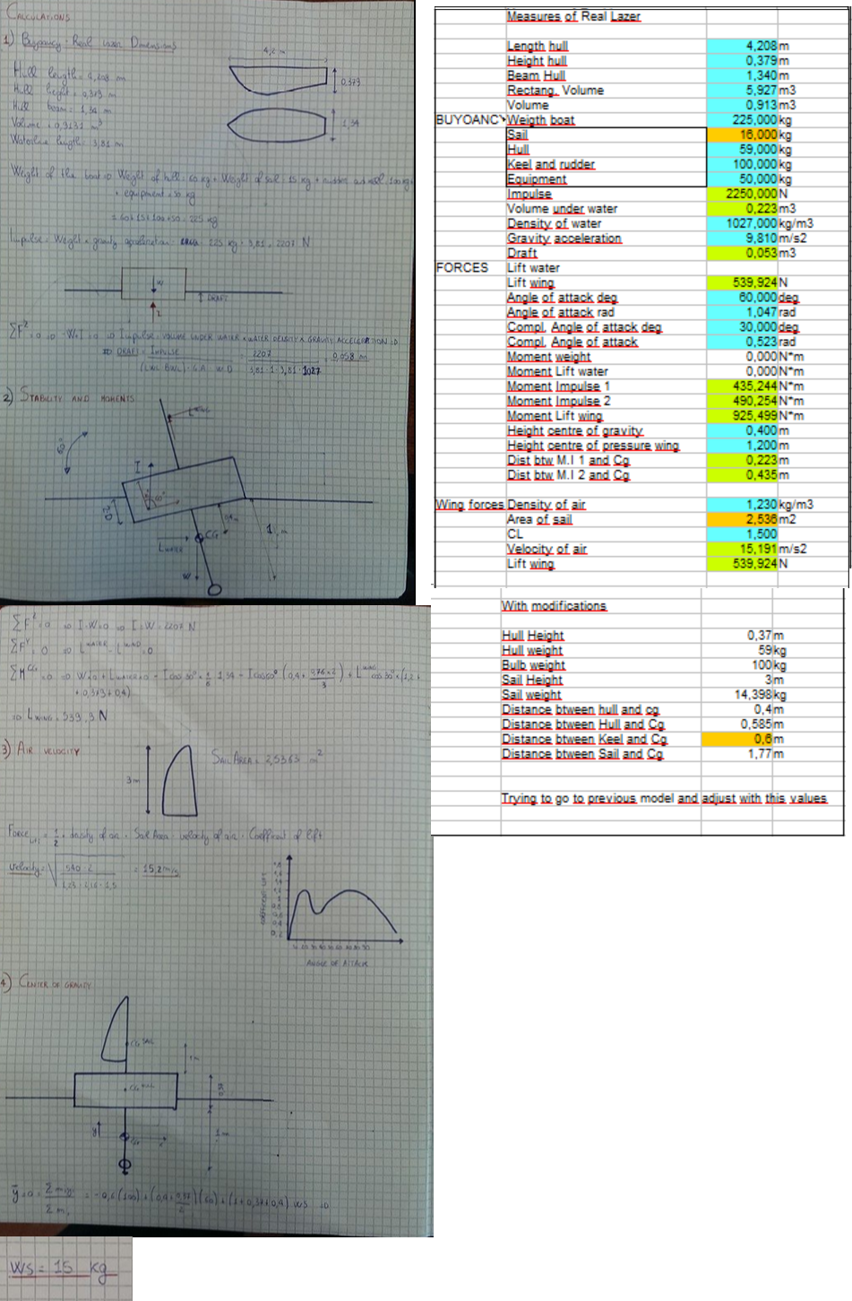
7.4 Possible Coverage Materials and Manufacture Processes
In this section the manufacturing processes for several materials will be scrutinised individually to develop a well thought out material for the sail coverage area. The comparison of materials is our main consideration as this will need lightweight, but structurally secure properties to continue on to the manufacturing stage. Manufacturing must also be defined according to our level of craftsmanship, time to complete each task and the final product assembly. This chapter will highlight the following:
- Manual Lamination
- Wood Assembly & Bonding
- Metal Assembly and Bonding
7.4.1 Manual Lamination
The first idea was to build a wing sail in composites materials with the process of manual lamination. The manual lamination is the older and easier process for composites materials. The dry fibres, which may be of different types from glass to carbon, in the form of unidirectional, or multi-axial fabric, are arranged in / on a mould previously treated with a release agent and impregnated by hand with the resin (epoxy, vinyl ester or polyester). Using rollers and spatulas to force the resin between the tissues generally does this procedure. Subsequently, the laminate is left to cure at room temperature. If the thickness of the laminar is high, lamination can be carried out in several stages to be sure that the fibres are well wetted by the resin. The last layer is generally laminated with a layer of peel-ply, that is, a film that has releasing properties and has the function of absorbing part of the excess resin, ensuring a better surface finish and protect the surface from contamination in the event that the product both left catalyse in poorly cleaned. The mould is said female if the fibres are arranged within it, male if they are arranged on them; or, in the case of lamination of a hull of a vessel, the contact surface of the mould will be the inner surface in the case of a male mould, the outer surface in the case of the female mould. Considering that the contact surface of the mould generally has a much smoother finish than the other, it follows that to achieve the same level of finishing vessel produced in the male mould will require a greater number of hours of work than using a female mould.
7.4.1.1 Fiberglass
Fibreglass is a small glass filament, they consist mostly of silicon oxides, which are layered together to produce a high strength to weight ratio. The spectrum of its characteristics can be modified by mixed with other oxides such as aluminium or magnesium. The glass filaments are classified according to the type of glass used for manufacturing, these being the A, E, C and S.
The advantages of this material are extensive, from high strength to weight ratio with a increased life and is structurally and dimensionally stable under substantial loads. These advantages does come at a cost, the price is increasingly greater than other prospected materials and the fibreglass might be wasted somewhat due to our inexperience in working with such a material.
7.4.1.2 Resin
Resins are plastic materials consisting of polymers of a high molecular weight. The polymer can be used without additives, these are added in order to improve properties mechanical, thixotropic or modify any other characteristic. Some of the characteristics that these polymers are their low weight, electrical insulation, corrosion resistant and adhesive properties. The main function of the resin or matrix, is to support the applied load and transmit the reinforcement through the interface, for this matrix must be deformable. It must also protect fibres and keep the external environment and tightly bound. The resins may be thermoplastic or thermoset, depending on whether or not crosslinking present.
We will focus on thermosetting resins; can be classified according to their properties into three groups:
- Epoxy is known in the marine manufacture for its good toughness and bonding strength. Quality epoxy resins stick to materials with 2,000-p.s.i. Vs. 500-p.s.i. for vinyl ester resins and less for polyesters. In areas that must be able to contract and strain with the fibers without micro fracturing, epoxy resins offer much greater capability. Cured epoxy tends to be very resistant to moisture absorption. Epoxy resin will bond dissimilar or already-cured materials which makes repair work that is very reliable and strong. Epoxy actually bonds to all sorts of fibres very well and also offers excellent results in repair-ability when it is used to bond two different materials together.[114]
- Vinyl ester is stronger than polyester resins and cheaper than epoxy resins. Vinyl ester resins use a polyester resin type of cross-linking molecules in the bonding process. Vinyl ester is a hybrid form of polyester resin that has been toughened with epoxy molecules within the main molecular structure. Vinyester resins offer better resistance to moisture absorption than polyester resins but its downside is in the use of liquid styrene to thin it out and its sensitivity to atmospheric moisture and temperature. Sometimes it won't cure if the atmospheric conditions are not right. It also has difficulty in bonding dissimilar and already-cured materials.
- Polyester is the cheapest resin available in the marine industry and offers the poorest adhesion, has the highest water absorption, highest shrinkage, and high VOC's. Polyester resin is only compatible with fiberglass fibres and is best suited to building things that are not weight sensitive. It is also not tough and fractures easily. Polyesters tend to end up with micro-cracks and are tough to re-bond and suffer from osmotic blistering when untreated by an epoxy resin barrier to water.
Although all of these thermosetting resins may be suitable corresponding to our weight it lacks the ability to perform adequate structural support to the wing. Its flexural tendencies is to great for the wing-sail and may easily damage in operating conditions, also the plastics may deteriorate overtime due to its inability to withstand UV rays.
7.4.1.3 Mylar
The Mylar A has an average tensile strength of about 190 MPa, and excellent moisture resistance to most chemicals and withstands temperatures from -70°C to + 150°C. Because it contains no plasticisers, the Mylar A does not become brittle used under normal conditions. This is the material that could be used to cover and giving continuity to the sail over the composite structure. It also has its flaws as Mylar can easily rip, if this was to happen in operation the boat may lack the ability to manoeuvre and must be retrieved in Open Ocean or other surroundings. It is also a problem to apply the Mylar to the wing due to the wings size and the lack of equipment such as a heat gun.
7.4.2 Cutting and Bonding Wood
The second idea is to use wood, in particular maritime plywood for the main structure, or rather for the ribs and the first skin. Marine plywood is a particular type of plywood that is commonly used in marine applications. It is composed from select grades of wood. Using this type of plywood can provide you with a number of benefits. A good quality marine plywood sail, well constructed and protected will be immensely strong and last a lifetime. Plywood is particularly pliable, this type of wood can be bent and still maintain its structural integrity. Marine plywood also provides good impact resistance. The outside layer of the plywood is highly hard and dense. This means that if something hit it, it will not necessarily dent or break. Wood is pretty easy to work with, on the condition that you have the proper tools for the different tasks. The precision of the cut depends on the blade and also on the precision of the worker. A circular saw or a jig saw are ideal for cutting panels of plywood, however, even in the absence of these, we can reach good results using a cutter. The operation is not trivial to make and serve a good dose of patience, care and precision for big panels of plywood.
Adhesives will be a primary fastener for the wooden structure, there is a wide selection of glue on the market therefore our selection must be rigorous and very selective to ensure it meets all the specifications to withstand the environments it will be subjected too. The adhesive must be very strong, waterproof, and suitable for exterior use and, to some extent, solvent tolerant.
| Product | Type | Specification | Cost |
|---|---|---|---|
| Titebond III Ultimate Wood Glue | Wood Glue | Waterproof formula, Exterior and Interior use, Conforms to ASTM D-4236, Superior strength - Strong initial tack, Unaffected by finishes. | €7 |
| Sikaflex 292 | Polyurethane | Used for structural bonding applications and suitable for dynamically stressed constructions. The paste-like material cures on exposure to atmospheric moisture to form a durable. | €23 |
| Loctite Epoxy Heavy Duty | Epoxy | High impact resistant, Water resistant but not recommended to be subjected to water for extensive periods of time, Set in 5-10 minutes. This glue is also sold in small quantities. | €18 |
The Sikaflex 292, is specifically designed for structural bonding in boats it addresses all aspects which we need for the joining of the ribs and skin. It offers a vast amount of properties all of which exceed the expectations of the competitors on the market. The one component polyurethane adhesive of thixotropic, paste-like consistency that cures on exposure, it can be easily applied using a caulking gun this method of application is later described in section, 7.4 Manufacture Process.
Features and Benefits
- Elastic
- High mechanical load capacity
- Can be used in spatula application
- Tolerance gapping
- Vibration dampening
- Hydrolysis resistant
- Solvent free
- Wide adhesion range
| Technical Properties | |
|---|---|
| Colours | White |
| Tack-free time* | 40 minutes approx. |
| Elongation at break | 300% approx. |
| Tensile-shear strength | 2.0 MPa approx. |
| Tensile strength | 2.0 MPa approx. |
| Application temperature | +10°C to +40°C |
| Service temperature (continuous) short term (up to 4 hours) | -40°C to +90°C +120 °C |
| Shelf life (stored below 25°C) Method of application | 12 months Hand- or air- gun |
(* = at 23°C and 50% relative humidity)
Sikaflex 292 is chemically resistant to fresh water, seawater, limewater, sewage effluent, dilute acids and caustic solutions; temporarily resistant to fuels, mineral oils, vegetable and animal fats and oils; not resistant to organic acids, alcohol, concentrated mineral acids and caustic solutions or solvents. Brief contact with fuels and lubricants has no significant effect. [Sikaflex, 2002]
7.4.3 Working with Metal
7.4.3.1 Aluminium
Metallic aluminium has many properties that make it useful in a wide range of applications. It is lightweight, strong, nonmagnetic, and nontoxic. It conducts heat and electricity and reflects heat and light. It is strong but easily workable, and it retains its strength under extreme cold without becoming brittle. The surface of aluminium quickly oxidizes to form an invisible barrier to corrosion. Furthermore, aluminium can easily and economically be recycled into new products. Aluminium is a much softer metal than iron and hence tools used to work with iron cannot be used for working with aluminium. However, hand tools used to work on wood can be used for aluminium too. Tools usually required for working with aluminium are cutting tools, drilling tools, polishing tools and fusing tools. Here there are some tools required for working with aluminium:
- Marking
- A scribe is a tool with a sharp edge that can be used to make straight markings on a metal surface, the use of this for our scale will be time consuming and lack a degree of accuracy. To mark hole positioning a centre punch can be used, this is a sharp-pointed rod made of iron and is used to mark positions for drilling holes. In this case, the centre punch is hammered in deep using a mallet to form a dent; this dent helps to keep the drill bit in place and to avoid slipping when drilling.
- Cutting
- Hand-held saws can be used for wood or hacksaws used for iron are quite adaptable to work on aluminium with a little tweaking in the choice of blades. The blades used when working with aluminium have to be wide-mouthed and made of high carbide, like with wood. This helps to keep the saw clear of burs and to give precise cuts. If cuts have to be made quickly and with less precision a guillotine may be used to cut small lengths with ease.
- Drilling
- Since aluminium is a softer metal, it has the tendency to clog the drill bit. So the drill bit used when working with aluminium has to be the type with wide spirals. Hand-held drills, the kind in which you can change the drill bit manually, both electric and manual, are great to work with on aluminium. In our circumstances industrial pillar drills can be used in the ISEP workshop that has a more precise jig for more accurate drilling.
- Bonding
- Aluminium can be bonded in a number of ways, from adhesive bonding riveting, bolt and screw. The adhesive process would mean the casing for the aluminium is sealed with great difficulty to separate when upgrades are required. The riveting process would be time consuming but offer a clean finish on the product maintaining the surface finish at its finest for the airfoil profile. Bolt and screw bonding is the best for DFA and DFD processes but takes a large quantity of time calculating and position the connection points without wing failure.
7.4.4 Conclusion
The analysis of different materials for the skin coverage of the wing has been highly debated among the team and advisors to deliver the best possible quality product to the client which fits in our skill sets and ability. We opted for wood, in particular maritime plywood, mainly for the following reasons:
- Maritime Plywood is inexpensive; with a limited budget the price of the raw materials is an important factor. Our Sail will be of considerable dimensions, and the quantity of material is remarkable and must be optimised to allow the client to fully benefit from their investment in our development of the wing product.
- Wood is malleable in terms of workability, wood doesn't need a mould, nor does it require specialised tools. The Maritime Plywood we will select is easily worked by a non-skilled worker and with basic but sturdy woodworking joints can well built in the construction of the wing.
- Wood is easily purchased not he market, there is a vast array of wood and all the related tools are present in all DIY shops like Leroy Merlin and Aki. At these local establishments the customer has the possibility to cut custom sizes of material reducing the workload and increasing the speed of the manufacturing process.
7.5 Components
After reviewing possible manufacturing processes and materials for the skin coverage considering the price and ease of manufacture for our teams variety of skill sets we will come to final material decision for each component. The final materials will be completed in the following section; this section will be filled with the possible and most suitable of each for our product.
7.5.1 Masts
7.5.1.1 Metal Mast
The Mast is the most important structural piece in our wing sail. It has the function to support all the profiles, to support the wind pressure and to transmit it to the hull. It has been decided in the previous chapter to develop a mast of two different materials to preserve the weight of the sail. The first metre of the mast will be constructed of metal and the remainder wood, the metal options are listed and compared in the table below.
| Property | Stainless Steel 316L vs. Aluminium |
|---|---|
| Strength & Malleability | Aluminium is more malleable and elastic than steel. Aluminium can go places and create shapes that steel cannot. Especially for parts with deep and straight walls, aluminium is the material of choice. Steel is a very tough and resilient metal but cannot generally be pushed to the same extreme dimensional limits as aluminium without cracking or ripping. |
| Cost | The price of steel and aluminium is continually fluctuating based on global supply and demand, fuel costs and the price and availability of iron and bauxite ore; however steel is generally cheaper than aluminium. The cost of raw materials has a direct impact on the price of the finished spinning. |
| Corrosion Resistance | Aluminium’s greatest attribute is that it is corrosion resistant without any treatment. Aluminium doesn’t rust. With aluminium there is no paint or coating to wear or scratch off. Steel or “carbon steel” in the metals world (as opposed to stainless steel) usually needs painted or treated to protect it from rust and corrosion, especially if the steel part will be at work in a moist, damp or abrasive environment. |
| Weight | Steel is harder than aluminium. Steel is strong and less likely to warp, deform or bend under weight, force or heat. Nevertheless the strength of steel’s trade-off is that steel is much heavier therefore has a higher density than aluminium. Steel is typically 2.5 times denser than aluminium. |
It is a clear decision to use stainless steel 316L due to these points stated above, the strength of the material opposed to aluminium is a better fit for our design purpose. Now deciding a diameter and thickness of a stainless steel mast is our task, the material sourced has a Yield Strength of ${290}$ MPa. This is the maximum value of stress before plastic deformation begins and as the wing is allowed to move freely it is an alternating and fluctuating stress that increases the chances of failure. It was decided to source a material with 70 mm diameter and 3 mm thickness, from this the Moment of Inertia value must be calculated to find the maximum possible stress the boat will operate before failure under. The dimensions of the stainless steel mast are obtained with the following equations:
- Assuming a Force of $2000 N$ and a mast length of $1.2 m$ we reach with the Equation \ref{eq:steel}
\begin{equation} Moment = \frac{Force \times Distance}{1000} = 2400 Nm \label{eq:steel} \end{equation}
- Assuming a Maximum Allowable stress of stainless steel of $290 MPa$, we reach with the equation \ref{eq:steel2}
\begin{equation} W = \frac{Moment}{Max Allowable Stress}\times 1000 = 8.275 \times {10}^{3} {mm}^{3} \label{eq:steel2} \end{equation}
- With the value of W we can reach the dimensions by accessing a table with solution values. As already mentioned the dimensions reached are a diameter of $ 70 mm $ with a thickness of $ 3 mm $.
Figure 135

- The Moment of Inertia can be calculated for the stainless steel mast by using the following equation \ref{eq:steel3}
\begin{equation} I = \frac { 3.1415{d}^{4}}{64} = \frac { 3.1415 \times {d_o}^{4} - {d_i}^{4}}{64} = \frac { 3.1415 \times {70}^{4} - {64}^{4}}{64} = 355027\times {10}^{-12}{m}^{4}. \label{eq:steel3} \end{equation}
Now that a value has been found for the Moment of Inertia, $ I = 355027\times {10}^{-12}{m}^{4} $, we can use this in the bending moment equation to discover the maximum allowable force on the metal mast before plastic deformation occurs.
- The bending moment equation is the following \ref{eq:steel4}
\begin{equation} σ = \frac { {M}{y}}{I} \label{eq:steel4} \end{equation}
- The previously stated yield stress, $ {Y_s} = 290 MPa $ of Stainless Steel 316L will be used in the bending moment equation to solve the largest force available on the shaft. The assumed maximum from wind pressure will not exceed, $ M = 2000 N $. Other information required is $ y = 0.035 mm $, this is acquired from the mast profile seen in 122.
$ {σ} = \frac { {M}{y}}{I} = {σ} = \frac { 1.2\times {2000}\times {0.035}}{355027\times {10}^{-12}} = 236.601 \times {10}^{6} Pa = 236.601 MPa $
- This value does not exceed the yield stress value stated above although it can offer us vital information for the Factor of Safety, FoS of our deformation value. This can be seen in the following equation \ref{eq:steel6}
\begin{equation} FoS = \frac { {Y_s}}{σ} = \frac { {290\times {10}^{6}}}{236\times {10}^{6}} = 1.22 \label{eq:steel6} \end{equation}
This factor of safety value of 1.22 indicates the probability of failure due to bending. It is vital for failure criterion to be addressed as the material may not be suitable and thus a waste of investment and design time. This proves the mast dimensions as a viable design aspect of the rigid wing sail.
The mast will also require an adequate connection to the main hull body, to accomplish this flange bearings must be purchased to accommodate the 70 diameter shaft to the modified hull. The decision to connect these components in this manner will allow for mast rotation and improve the practically of installation and assembly for the user. The flange bearings are suitable for aquatic conditions thus suitable for the ocean conditions of the boat. The Figure 136 below indicates the type of bearing and the dimensions suitable for the selection of mast connections.
Figure 136

This bearing's installation can be seen in section 7.8.1 Mast Rotation along with the configuration to limit its rotation.
7.5.1.2 Main Wooden Mast
A wooden mast has been developed to reduce the weight of the wing sail while maintaining structural stability, it will take the form of an I Beam. To ensure structural stability and to avoid failure we will calculate the moment of inertia required for the mast to withstand the following forces with the wood property, we assume the following:
- Maximum allowable wind pressure of $500 \frac{N}{{m}^{2}}$ .
- Tensile strength of wood to be ${60}$ MPa, with a security coefficient of $2$; so the maximum allowable stress used will be $\frac{60}{2}=30 MPa$
- Area of the sail (starting from the 3rd rib to the last) of $ 1.33 m^2 $ and an height of the centre of pressure of $0.7$ m
These assumed values can be used to calculate the moment at which it occurs on the wing at a certain position and therefore, the modulus of resistance.
- The moment at this point on the sail is found in the equation \ref{eq:wood1}
\begin{equation} 500 \frac{N}{{m}^{2}} \times 1.33 {m}^{2} = 669 N \rightarrow 669\times 0.7 = 468 Nm \label{eq:wood1} \end{equation}
- The modulus of resistance can be found with equation \ref{eq:wood2} to be equal to
\begin{equation} W = \frac { M }{ \sigma } =\frac { 468 Nm }{ 30\times { 10 }^{ -6 } } = 15.6\times { 10}^{ -6} \label{eq:wood2} \end{equation}
- With a width of the rib of $0.19 m$ we reach a value for Inertia using the bending moment equation \ref{eq:wood3}
\begin{equation} I_=\frac { M\times Y }{ \sigma } =\frac { 468 Nm \times 0.095 m }{ 30 MPa \times { 10 }^{ -6 } } = 1.56\times { 10}^{ -6} {m}^{4} \label{eq:wood3} \end{equation}
This value of ${Ixx} = 1.56\times { 10}^{ -6} {m}^{4}$ is the minimum value acceptable for the Moment of Inertia, therefore we must source and build materials to specific sizes to overcome this value. The design requires two I Beam masts, one for the main sail and the other for the stabilizer. In Figure 137 the main sail I beam can be seen followed by calculations, which prove our dimensions selection and for the main wooden mast as the value of the moment of inertia greater than $1.56\times { 10}^{ -6} {m}^{4}$.
Figure 137

Moment of Inertia on X & Y Axis
- The primary mast has a central piece of plywood of thickness, $ 8 mm $ this will give a value of inertia for section 1, given by equation \ref{eq:wood4}
\begin{equation} {Ix_1}=\frac { b\times{ h }^{ 3 } }{ 12 } =\frac { 0.008 \times { 0.154 }^{ 3 } }{ 12 } = 2.434\times {10}^{-6} {m}^{4} \label{eq:wood4} \end{equation}
- The 4 corners of this I beam have a width and breadth of $ 0.018 m $, this will give an inertia value for sections 2 and 3, given by equation \ref{eq:wood5}
\begin{equation} {Ix_2} =\frac { 0.044 \times { 0.018 }^{ 3 } }{ 12 } = 0.021\times {10}^{-6} {m}^{4} \label{eq:wood5} \end{equation}
- The area for both section 2 and 3 have been found using the standard area equation for a rectangle given by \ref{eq:rect}, which is identical to $ {A_3} $
\begin{equation} {A_2} = l \times b = 0.044 \times 0.018 = 7.92 \times {10}^{-4} {m}^{2} \label{eq:rect} \end{equation}
- The value of $ {d} $ is found from the distance between central axis of section 1 to the central axis of either section 2 or 3.
$ {d} = 0.086 $
- This calculation is used to find the area moment of inertia in the x-axis, which is found with equation \ref{eq:wood7}
\begin{equation} {Ixx} = {Ix_1}+2({Ix_2} + { A_2 } \times { d_2 }^{ 2 }) =2.434\times {10}^{-6} {m}^{4}+2( 0.021 \times {10}^{-6} {m}^{4} + {7.92 \times {10}^{-4} {m}^{2}} \times ({ 0.086 })^{ 2 }) = 1.42 \times {10}^{-5} {m}^{4} \label{eq:wood7} \end{equation}
This value for the area moment of inertia in the x-axis is by far greater than $ 1.56\times { 10}^{ -6} {m}^{4} $ which indicates that the masts geometry is suitable for the forces that will be applied in these locations.
- This equation is used to find the area moment of inertia in the y-axis, found by the equation \ref{eq:wood8}
\begin{equation} {Iyy} = \frac{ {h_1}{b_1}^{ 3 } + {h_2}{b_2}^{ 3 } + {h_3}{b_3}^{ 3 }}{ 12 } = \frac{ {0.154} \times {0.008}^{ 3 } + {0.018} \times {0.044}^{ 3 } + {0.018} \times {0.044}^{ 3 }}{ 12 } = 0.262\times { 10}^{ -6} {m}^{4} \label{eq:wood8} \end{equation}
7.5.1.3 Stabiliser Wooden Mast
Now the stabilizer mast calculation can be found below along with figure 137 of the mast size dimensions. These values do not have to adhere to a moment of inertia at this current moment in time, the detachable stabiliser can be positioned differently according to the conditions the sail is operating under.
Figure 138

- The central piece of plywood for the stabiliser has a of $ 4 mm $ this will give a value of inertia for section 1, given by the same equation \ref{eq:wood4} in the chapter above.
$ {Ix_1}=\frac { b\times{ h }^{ 3 } }{ 12 } =\frac { 0.004 \times { 0.052 }^{ 3 } }{ 12 } = 4.69\times {10}^{-8} {m}^{4}$
- The 4 corners of the I beam have a width and breadth of $ 0.009 m $, this will give an inertia value for sections 2 and 3, given by the same equation \ref{eq:wood5} in the chapter above.
${Ix_2} =\frac { 0.022 \times { 0.009 }^{ 3 } }{ 12 } = 1.3365\times {10}^{-9} {m}^{4} $
- The area for both section 2 and 3 have been found using the standard area equation for a rectangle \ref{eq:rect}, which is identical to $ {A_3} $.
$ {A_2} = l \times b = 0.022 \times 0.009 = 1.98\times {10}^{-4}{m}^{2} $.
- The value of $ {d} $ is found from the distance between central axis of section 1 to the central axis of either section 2 or 3.
$ {d_2} = 0.0305 $
- This calculation is used to find the area moment of inertia in the x-axis, given by the same equation \ref{eq:wood7} in the chapter above.
$ {Ixx} = {Ix_1}+2({Ix_2} + { A_2 } \times { d_2 }^{ 2 }) = 4.69\times {10}^{-8} +2 (1.3365\times {10}^{-9} + 1.98\times {10}^{-4} \times (0.0305)^{ 2 }) = 0.418\times {10}^{-6} {m}^{4} $
- This equation is used to find the area moment of inertia in the y-axis, given by the same equation \ref{eq:wood8} in the chapter above.
$ {Iyy} = \frac{ {h_1}{b_1}^{ 3 } + {h_2}{b_2}^{ 3 } + {h_3}{b_3}^{ 3 }}{ 12 } = \frac{ {0.052} \times {0.004}^{ 3 } + {0.009} \times {0.022}^{ 3 } + {0.009} \times {0.022}^{ 3 }}{ 12 } = 1.625\times { 10 }^{ -8 } {m}^{4} $
7.5.2 Skin Coverage
7.5.2.1 Maritime Plywood
The previous chapter has allowed us to select maritime plywood as our skin coverage of the sail. Primarily fabrics and plastics (Mylar in particular) are used in traditional sails but due to the rigidity of our sail maritime plywood has been selected. The coverage gives continuity to the structure and creates the wind lift. Here analysed the pros and cons of the our selection of maritime plywood:
| Property | Maritime Plywood |
|---|---|
| Weight | The sourced plywood has a density of 540 kg/m3, and is difficult to find less thick than 3mm. Thus we have selected 4mm. |
| Waterproof | Plywood used in boats and sails must be made with waterproof, although considered ‘maritime’ it can still be damaged by the environment. Also the bonding adhesive must be waterproof, otherwise the structure will fail. |
| Applying | Plywood applications will be difficult to structure, with the preparation of moulds and adequate adhesive. The selected adhesive, Sikaflex 292 apply to all properties of boat construction. |
| Structural strength | Plywood adds the appropriate structural strength although this comes at a cost of weight to the sail. |
We opted in this case for the maritime plywood mainly for its high resistance given to the structure. However as mentioned above, a complete skin in plywood means it will weigh a total,
$\frac{Sail Area}{Plywood Density \times Thickness} = \frac {5.2 {m}^{2}}{540 kg/{m}^{3} \times 4 mm} = 2.4 kg $
Saving weight will be vital to in the reduction of the wing weight therefore we plan to cut the plywood skin in proximity of the ribs and the outer coverage as we prepare to replace these cut outs with pre-treated plates of balsa.
7.5.2.2 Balsa
Balsa wood is very soft and light, with a rude, open grain. The density of dry balsa wood is extremely small and perfect for our replacement on the wing in comparison to the maritime plywood. The proposition is to replace the plywood with pre-treated balsa.
The balsa will be initially bought in 1 m panels and exposed to epoxy resin to harden the shell this will increase the rigidity while maintaining flexibility, this idea will allow for the material to be optimised for our purposes. This will later be addressed in the section 7.3 Manufacture Process. This crafty alternative should become possible as balsa is know to have a tendency to soak up large quantities of material on the initial coats but for our purposes may become sufficient in applying the effect required for our rigid-wing sail. Balsa generally should not be used to hold nails, with glue being the preferred method of joining which is also accommodated for our design proposal.
7.5.3 Ribs
The ribs are the structural integrity of the wingsail, without stability here the product will fail once manufactured. Great care has been taken researching materials and both maritime plywood and fiberglass. The structural bonding for both materials varies indefinitely, the plywood ribs must be fixed to the mast and coverage skin with Sikaflex 292 (Polyurethane) Glue
For the ribs we choose Maritime Plywood. It has good resistance, and the weight of the ribs is not so influencing in the entire structure. Plywood is cheaper and easier to work than aluminium and composites, although our main selection of this material was down to the accessibility. We will acquire the same material for the skin this it will be easily bought and cut to achieve the required sizes while maintaining the requirements to be structurally sound. The reason for not selecting composites is that they require a mould that is too expensive to manufacture for just one component and aluminium requires specific tools to work with, which we do not have access too. This shows the maritime plywood to be the best consideration for our wing-sail considering our level of experience and budget. The materials does has its flaws and will not be fully protected from the environment, much like the coverage a layer of protective paint will be applied to prevent damage over time.
7.5.4 Stabiliser
7.5.4.1 Stabiliser Material
The stabilisers material will be made from a combination of plywood and balsa much like the main sail, and it will be cut and from primarily the same approach. It is estimated that the weight of the stabiliser will not branch over 2.5 kg. This value is suitable to be held by the stabiliser beam that is discussed in the following section.
7.5.4.2 Stabiliser Beam
The stabiliser beam is valid from same considerations we did above for the mast. We opted for a stainless steel bar (316L), to have the same provider of the mast. We decided to have three pieces instead of one to have the possibility to regulate the length, with the purpose of balancing the weight of the stabilizer. We opted for a central part with a diameter of 33 millimetres, with the two adjustable bars smaller with a diameter of 30 mm.
7.5.4.2 Stabiliser Movement Device
The stabiliser will be moved by a servomotor later stated in this section under, 7.5.5.5 Servo Motor. The servomotor will be positioned in a central rib to give it vital control, where it will be connected to a vertical shaft which can rotate to an angle of ±20° from 0°. The shaft will be held into position by flange bearings positioned in-between each rib, these flanges can be seen in Figure 139 below.
Figure 139

7.5.5 Electrical Devices
7.5.5.1 Battery
We are using a battery to supply the actuator, servomotor, wind sensor, navigation lights, and the controlling system of the boat. Our battery is a Lead Acid battery (2.5.1 part of the state of the art). The battery supplies 12V voltage, which is supported by the most of devices, what we need. We suggest the ULS5-12 type of the Ultracell batteries. It has 5Ah (Ampere-hour) normal capacity in 20 hours. It is a long-term battery, the design floating time is 5 years in 20 °C. The datasheet of the battery is located in this website: http://ultracell.net/datasheets/UL5-12.pdf. We suggest buying this type of battery at this portuguese store: Castro Electrónica, http://www.castroelectronica.pt/.
Figure 140 displays the battery from Ultracell, what we suggest to use.

7.5.5.2 Navigation Lights
The International Regulations for the Prevention of Collision at Sea (COLREGS) apply to all vessels upon the high seas and vessels on most waterways, bays, inlets, rivers connected to the sea.
| Rule Number | Rule Statement |
|---|---|
| Rule 3a | Defines 'Vessel' as all manner of watercraft used or capable of being used as a means of transportation on water. |
| Rule 20 | States that all vessels must display the proper lights from sunset to sunrise and in situations where there is limited visibility. |
| Rule 21a | Masthead Light: The 'masthead light' is a white light placed over the fore and aft centreline of the vessel showing with an arc of 225 degrees. |
| Rule 21b | Sidelights: Sidelights are red (port side) and green (starboard side) lights than shine in an arc of 112.5 degrees from straight ahead to a point 22.5 degrees abaft the beam. |
| Rule 21c | Stern Light: The stern light is a white light placed as near as is practicable at the stern. The light shines in an arc of 135 degrees. |
Figure 141 COLREGS Regulations

A sailboat under the dimensions of 20m is allowed to have the sidelights as a two-colour lantern or to have all three lights in a three-colour lantern. It hast to be located at the top oft the mast or as close as possible to the top. Furthermore it does not need a stern light. [Carsten Seebach, 2015]
Figure 142 displays the location where we plan to install the light


Lastly we had to find a suitable light that fulfils all regulations and is at the same time not too big, as our space on top of the sail is limited. Therefore we decided to search for a tri-colour light that will include all lights that are needed.
Figure 143 shows the light that we are planning to purchase.


This light will be possible to purchase at: mundodanautica.com
7.5.5.3 Wind Sensor
For the wind sensor we are looking for a compact sensor for wind direction and also the wind velocity. The reason is as for all our electrical components that we only have limited space and are trying to reduce the weight to a minimum. As we already analysed different types of wind sensors in chapter 2.5.3.1 Wind Sensor, we decided now for a of a cup anemometer that includes a wing for the wind direction. On the one hand this product is possible to purchase in Portugal, which was one of the main restrictions and also combines both needed measured values. Although we firstly favoured the AMS AS504X encoders we now had to find a sensor that is purchasable and does not need to be build. Second in our list was the Propeller vane anemometer, which is not too expensive, is compact and also very accurate but we could not find any supplier for this. Lastly our choice that you can see in Figure 144 is an agreement of all aspects mentioned before.
Figure 144 is a picture of the wind sensor that we found to purchase in Portugal.


The website of the company that is located in Braga to purchase this sensor is: priac.com.pt
However, we see a problem with this wind sensor. As we already explained in chapter 2.4 Optimal Sail Position, we have the true wind approaching the boat and also due to our forward movement the apparent wind. This sensor will have problems with the differentiation of the apparent- and true wind as it will get distracted by the arising apparent wind. One solution for this is a sensor that can understand the different wind types and on this basis calculate the optimal sail position. Taking this into account, we looked at some solutions that other autonomous sailboats use. In our opinion the best but very expensive solution we found, ASVRoboat use the “Airmar PB200”. We could not find it in an online store in Portugal but it can be for example purchased on: www.lojatopbarcos.com. For a detailed information about this product you can see: http://www.airmartechnology.com/uploads/brochures/pb200.pdf.
7.5.5.4 Actuator
The actuator is the dispositive that creates the movement along a straight line, in contrast with the rotary motion of a conventional electric motor. This movement along a straight line ensures the movement of the jib.
Figure 145 is a picture of the actuator we suggest to buy.
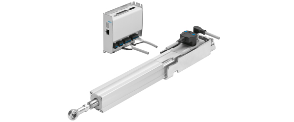
The parameters of choices for our actuator were:
- Dimension ⇒ We need a small actuator that can be installed over the central rib of the jib.
- Weight ⇒ In order to save weight it's fundamental to not have an over weighty actuator.
- Presence of the encoder ⇒ We need an actuator that can enable our jib to rotate around an angle of 40° (from -20° to 20°). The encoder is the dispositive that provide the actuator the information about the right positioning.
Our choice fell on an actuator provided by Festo. It is a mechanical linear drive with piston rod and permanently attached motor. The driving component consists of an electrically actuated spindle that converts the rotary motion of the motor into linear motion of the piston rod. In the table 34 the general technical data.
| Property | Value |
|---|---|
| Size | 40 |
| Male thread | M10*1.25 |
| Female thread | M8 |
| Working Stroke [mm] | 50 … 400 |
| Stroke reserve [mm] | 0 |
| Max.Torsion angle of the piston rod [°] | $<= \pm1$ |
| Position sensing | Via proximity sensor |
| Type of mounting | Via female thread |
Figure 146 is indicates the equation required to find the stroke length of the actuator.

- Displacement of the actuator, therefore actuator stroke length of 100mm, the maximum additional length to move the actuator to an angle of ± 20°.
equation \ref{eq:disp}
\begin{equation} {y} = {r} \times sin(20°) = {40} \times sin(20°) < 13.7mm ≈ 14 mm \label{eq:disp} \end{equation}
7.5.5.5 Servo Motor
Due to the need of moving the tail of the stabiliser to get the optimal sail position, we need a powered motor. This motor has to be controlled and moved without human interference. As our idea is to put the motor on one of the ribs, we have a limited space and also the motor will be limited in its weight. The maximum dimension for the motor will be 45x40mm and the type of motor we are looking for is an RC Motor that is mostly used for scale modelling. The HS-5646WP Servo Motor is the model we would suggest to buy. Although we haven't found it on a Portuguese website yet, it is possible to purchase it on: http://hitecrcd.com . The benefits of this type of RC Model are that it is waterproof and also creating a high torque while still in the limitation of the dimensions.
Figure 147 is a picture of the RC Motor we suggest to buy.

7.5.5.6 Solar Panel
To charge the battery when our system is working in the sea, we need a solar panel, because it cannot be charged by the electrical power system. In addition, we do not need AC/DC converter, because the solar panel supplies DC voltage to the battery, which also supplies DC voltage to our devices on the boat. To recharge the battery we will need two, flexible, thin film solar panel, which will be located on each side of the sail. Our choice is the polycrystalline type that we decribed in chapter 2.5.2 State of the Art. These panels are suitable for marine use, because their laminate coating on the exterior of the panel makes it impervious to saltwater, rain, and other weather elements. The solar panel has a completely waterproof junction box. Our choice and recommendation is the AP50-2 solar panel, it is possible to buy here: http://www.eco-worthy.com/
Solar Panel Specifications:
- Rated power: 50 W
- Maximum voltage: 18 V
- Maximum current: 2.78 A
- Module size: 767 mm*506 mm*2.5 mm
- Cell efficiency: ≥18 %
- Net weight: 1.85 kg
Figure 148 displays the flexible solar panel, we suggest.

7.6 Materials List
The production of a materials list to quantify costs, quantity and weight of each material required is a necessity for our project management agenda and to conform to our eco-efficiency goals in the selection of appropriate materials. This will push us towards following the predetermined design architecture and in-depth manufacturing process that is further elaborated in the following section. In allowing a distinct differential between the data collected on each component separate tables were prepared to ease the purchasing process, three tables were fabricated, a parts list, accumulated price list and finally the suppliers contact information which can be seen in this section.
| Part | Material | Quantity | Weight /unit (kg) | Total weight (kg) | Total weight utilized (kg) | Price/unit (€) | Total Price (€) | Supplier |
|---|---|---|---|---|---|---|---|---|
| Mast | Stainless Steel (316L) (Tubo Inox Milimétrico) | 1 Cylinder (1000x70x3) | 5.033 | 5.033 | 5.033 | 5.00 | 5.00 | Tubinox |
| I Beam Spars /Lateral Union | Wood (Pinho) | 6 Strips (2400x18x18) | 0.13 | 0.78 | 0.65 | 3.39 | 20.34 | AKI |
| Stabiliser I Beam Spars | Ripa Aplainada | 1 Strips (2400x12x12) | 0.13 | 0.13 | 0.1 | 1.79 | 1.79 | Leroy Merlin |
| Ribs (Main Wing 8 & Stabilizer 4) | Maritime Plywood B/BB C3 (4mm) | 1 Plate (12 ribs) (3100x1530x4) | 11.19 | 11.19 | 2 | 66.67 | 66.67 | Madeivouga |
| Wing Jib, skin & stabilizer cover | Maritime Plywood B/BB C3 (4mm) | 2 Plates (3100x1530x4) | 11.19 | 22.38 | 6 | 66.67 | 133.33 | Madeivouga |
| Extra Wing Coverage | Balsa 2mm | 50 Plates (1000x100x2) | 0.032 | 1.6 | 1.6 | 1.69 | 84.50 | Leroy Merlin |
| Hinge | Stainless Steel | Dobradica Piana Inox (1000mm) x2 | - | - | - | 6.92 | 13.84 | Leroy Merlin |
| Stabilizer bar (1) | Stainless Steel (316L) | 1 Cylinder (1500x30x1.5) | 1.070 | 1.605 | 1.2 | 7.50 | 15.00 | Tubinox |
| Stabilizer bar (2) | Stainless Steel (316L) | 1 Cylinder (1500x33x1.5) | 1.183 | 1.775 | 0.8 | 7.50 | 15.00 | Tubinox |
| Stablizer Flange | iglide® G – Flange Bearing | 12 (No: GFM-0810-050) | - | - | - | 2.69 | 32.28 | IGUS |
| Mast Flange | iglide® H370 – Flange Bearing | 2 (No: H370FM-7075-50) | - | - | - | 20.74 | 41.48 | IGUS |
| Mould | MDF | 2 Pieces (2440x1220x19) | - | - | - | 30.99 | 61.98 | Leroy Merlin |
| Glue | Sikaflex 292(Polyurethane) | 3 Packs | - | - | - | 23.00 | 69.00 | Vitorinox |
| Electric Linear Actuator EPCO [120] | w/ Stroke ?? & Force ?? | 1 | ? | ? | ?? | ?? | ?? | Festo |
| Battery | Ultracell UL 5AH – 12V | 1 (90x70x107) | 1.62 | 1.62 | 1.62 | 15.00 | 15.00 | Castro Electronica |
| Wind Sensor | Airmar PB200 Station Raymarine | 1 | - | - | - | 1409.00 | 1409.00 | Loja Top Barcos |
| Servomotor | HS-5646WP Waterproof Servo (12.9 kg Torque) | 1 (41.8 x 21x 40) | 0.061 | 0.061 | 0.061 | 70.00 | 70.00 | Hitec Multiplex |
| Navigation Light | Tricolour Light (M: 1LAZ30429) | 1 (125x170x44) | - | - | - | 34.98 | 34.98 | Mundo da Nautica |
| Cable | Copper Wire | 1 (8000×5) | - | - | - | 9.99 | 9.99 | Leroy Merlin |
| Cable Duct | PVC Cylinder | 1 (3000x32x1) | - | - | - | 1.99 | 5.97 | Leroy Merlin |
| Epoxy Paint | Titan Epoxy Paint | Primario Epoxy x1 | - | - | - | 23.29 | 23.29 | Leroy Merlin |
| Polyurethane Paint | Titan Polyurethane Paint | Verniz Marinho Tinta Yate x1 | - | - | - | 32.99 | 32.99 | Leroy Merlin |
| Table Support for Manufacture | Cavalete Madeira 73 | Supports x3 | - | - | - | 3.49 | 10.47 | Leroy Merlin |
| Glue Protection Layer | Rolo Filme Protetor | 1 Roll | - | - | - | 6.99 | 6.99 | Leroy Merlin |
| Total | - | - | ≈ 18.1 kg | € ??? |
| Supplier | Unit | Quantity | Price |
|---|---|---|---|
| www.Aki.pt | Stripes Pine Wood (2400x18x18) | 6 | € 20.34 |
| www.leroymerlin.pt | Stripes Wood (2400x9x9) | 1 | € 1.69 |
| www.leroymerlin.pt | MDF (2400x1220x19) | 2 | € 62.00 |
| www.leroymerlin.pt | Balsa Panels (1000x100x2) | 50 | € 84.50 |
| www.leroymerlyn.pt | Dobradica Piana Inox (1000 mm) | 2 | € 13.84 |
| www.leroymerlin.pt | Primario Epoxy for wood | 1 | € 23.00 |
| www.leroymerlin.pt | Verniz Marinho Tinta Yate | 1 | € 31.00 |
| www.leroymerlin.pt | Cavalete Madeira 73 | 3 | € 10.47 |
| www.leroymerlin.pt | Rolo Filme Protetor (0.50×220 m) | 1 | € 6.99 |
| www.festo.com | Linear Actuator (Stroke ?/ Force ?) | 1 | € ??? |
| www.madeivouga.com | Maritime Plywood - B/BB C3 (4 mm) (3100x1530x4) | 3 | € 200.00 |
| www.igus.com | Stabilizer Flange Bearing | 12 | € 32.28 |
| www.igus.com | Mast Flange Bearing | 2 | € 41.98 |
| www.castroelectronica.pt | Ultracell UL 5AH – 12V Battery | 1 | € 15.00 |
| www.lojatopbarcos.com | Airmar PB200 Station | 1 | € 1409 |
| www.hitecrcd.com | HS-5646WP Servomotor | 1 | € 70.00 |
| www.mundodanautica.com | Navigation Tricolour Light | 1 | € 34.98 |
| www.leroymerlin.pt | Cable (8 m in Length) | 1 | € 9.99 |
| www.leroymerlin.pt | PVC Cylindrical Duct (3000 x 32 x 1) | 1 | € 5.97 |
| www.tubinox.pt | Stainless steel tube (1000x70x3) | 1 | € 5.00 |
| www.tubinox.pt | Stainless steel tube (1500x30x1.5) | 1 | € 7.50 |
| www.tubinox.pt | Stainless steel tube (1500x33x1.5) | 1 | € 7.50 |
| www.vitorinox.pt | Sikaflex 292 | 3 | € 69.00 |
| Total | ??? | € ??? |
| Supplier | Address | Contact No. | |
|---|---|---|---|
| Leroy Merlin | Rua C. C. Parque Nascente, Estrada Exterior da Circunvalação, 4435-481 RIO TINTO | gondomar@leroymerlin.pt | Tel: +351 22 48 50 100 or Wood Dep. Tel: +351 22 485 0100 |
| Tubinox | TubinoxFilpres - AÇOS INOXIDÁVEIS, LDA. Sede, Rua Silva Aroso, Lote, 9, Apartado 5051 – Freixieiro 4456-901 Perafita | geral@tubinox.pt | Tel: +351 229 999 520 |
| Aki | Aki Porto, Estrada da Circunvalação, 13941-13975, 4100-178 Porto | N/A | Tel: +351 22 616 5860 |
| Vitorinox | Vitorinox, Lda. Rua do Castanhal, 334, Zona Industrial da Maia I - Sector II, Gemunde, 4475-122 MAIA, PORTUGAL | info@vitorinox.pt | Tel: +351 229 437 800 or +351 229 015 707 |
| Madeivouga | Zona Industrial de Taboeira - Apartado 724, 3801-801 Aveiro, Portugal | encomendas@madeivouga.pt | Tel: +351 234 300 800 |
| Festo | Festo - Automação, Unipessoal, Lda. Rua Manuel Pinto de Azevedo, 567, Apartado 8013, 4109-601 Porto, Portugal | encomendas@pt.festo.com | Tel: +351 226 156 150 |
| Castro Electronica | Rua da Alegria, 368, 4000-035 Porto | Email: porto@castroelectronica.pt | Tel: +351 222 087 798 |
| Hitech Multiplex | Crta De Navarcles Km, 4 5 Polig Ind Riu D Or, Nave 3 4 Santpedor, 08251 Spain | service@hitecrcd.com | +93-832-1860 |
| Mundo da Nautica | Mundodanautica - Equipamento de Náutica e Pesca de Recreio, Almofala de Baixo 3260-023 Aguda | info@mundodanautica.com | +351 236 628 235 |
| Loja Top Barcos | TopBoats Boat, Endereço da loja, Barcelona Road, No 53 Local 4 3 º andar, . Edifici o Rengle, CP 08302 Mataró, Barcelona, Spain | N/A | +93 758 62 99 |
| IGUS | Ctra. Llobatona, 6, Polígono Noi del Sucre, 08840 Viladecans, Barcelona, Spain | N/A | Tel.: +34 936 473 950 |
7.7 Manufacture Process
The manufacturing process has been planned ahead of the arriving materials to optimize our task allocation for each component, which is suited to a team members skill set. The forward planning has allowed us to optimize the equipment, material, time and roles of each member.
| Stage | Task | Team Member | Time (hours) |
|---|---|---|---|
| Preparation | Marking, Equipment Check and Glue Mold | Marc, Imre, Thies | 6 |
| Cutting | Wood and Metal | Marc and Jonny | 8 |
| Bonding | Dry and Wet Assembly | All Team Members | 24 |
| Electrical Devices | Fixing Devices and Supply Lines | Imre and Roberto | 4 |
| Finish | Sanding & Painting | Roberto, Thies, Jonny | 12 |
| Total Amount of Time | 54 |
7.7.1 Preparation
7.7.1.1 MDF Mould
The preparation before fixing the material together is a vital point in the manufacture stage. Due to the type of bonding we will use errors cannot be made at this stage, in removing these errors we took several precautions. Initially we will build two stands for the wing with a minimal degree of error as this will act as our mould. The stands will be made out of 19 mm thick MDF board and designed as shown below in Figure 149 .

This MDF mould is positioned 1.5 metres apart and in perfect alignment, these cannot move during the course of the manufacturing process to achieve perfect alignment in the sail.
7.7.1.2 Material Marking
Once arrived the maritime plywood sheets will be optimized fully by stencilling all material required for the coverage and ribs of both the main sail and stabilizer. Using the cavalete madeira tables we can keep these sheets level and in position while pencilling and cutting, these will be positioned equally to ensure stability.
7.7.1.3 Balsa Flexibility and Rigidity Improvement
During this time some of the balsa sheets will be placed in water overnight to allow the panels to soften and become flexible until the material dry’s. In this time the material will be positioned over a PVC pipe that has been cut in half, a weight is added to allow the balsa panel to follow the curvature of the pipe. This will allow the balsa to dry in this position and when applied to the leading edge of the rigid-wing sail reduce the brittleness of the material. The other balsa panels will be coated in an epoxy paint to increase the rigidity while maintaining the flexural properties required in the rigid-wing. These panels will dry for a period of 24 hours and be stored until required in the manufacturing section.
In doing almost the opposite, balsa panels will receive multiple coatings of epoxy resin and perhaps wood glue to increase the rigidity of the panel. These will be left over night and then receive a bend test to confirm the coatings are sufficient in taking the force of the wind. These epoxy/glue-coated panels will be used in replacing plywood throughout the wing in a solution to reduce the entire weight so that greater lift may be achieved. This solution will not take all the flexural properties away from balsa and allow it to form perfectly while maintaining great rigidity.
7.7.1.4 Equipment Checklist
All the equipment has been sourced from the workshop to ensure the manufacturing stage can be complete. The ISEP workshop has allowed us access to achieve the manufacturing process without outsourcing our blueprints to an available lazer cutting facility. In the workshop, with the help of Vitor we have found an array of tools and equipment, below is a listed table with the findings:
| Tool | Use | Quantity |
|---|---|---|
| Pillar Drill | Drilling holes of certain diameters vertically for precise holes, both in wood and metal | 1 |
| Hand Saw | Cutting wood | 3 |
| Hack Saw | Cutting Metal | 1 |
| Hand File | Remove small quantities of Metal/wood while offering a smoother finish | 1 |
| Electric Jigsaw | Cutting wood out of large sheets with ease | 1 |
| Sand Paper | Gradually smooth surfaces of wood/metal by the use of different grades | 10 |
| Pencil | Used to mark wooden surface to ensure precise lines for cutting | 4 |
| Wooden Stands | Elevate the wooden panels off the ground when cutting is being executed | 3 |
| Calking Gun | Pneumatic hand application tool for unipac glue, Sika 292 | 1 |
| Paint Brush | Apply all paint and finishing products to the sail | 2 |
| Gloves | Protection of hands during the glue and painting process | 4 |
| Vice | Holds metal/wood in position when working on, can be used to file/cut etc. | 1 |
| G-Clamp | Once adhesive is applied the G-clamp holds the I beam in position | 6 |
| Stanley Knife | Creating deep and accurate cuts almost any object | 2 |
7.7.2 Cutting Process
7.7.2.1 Coverage & Ribs
The cutting process must have a high degree of accuracy because minimal errors must be achieved when completing the wing. Using the predetermined stencils as a guide, the maritime plywood sheets are positioned on the cavalete madeira tables and cut using a electric jigsaw to precisely cut each rib and wing coverage. The blueprints for the wing coverage of the main wing, stabilizer and design of each rib can be seen in section 7.2.3 Final Wing and Boat Design.
These blueprints will be used as the stencils that can ensure the degree of accuracy required during the manufacturing stage. Once the outside perimeter of each rib is removed great care and attention must be taken when cutting the central proximity of the certain ribs.
7.7.2.2 I Beam Masts
The wooden mast for both the stabilizer and main wing will be made from a combination of maritime plywood and pinewood. The process of joining these two materials required an overnight bonding process, before this the central beam for each position (main sail and stabilizer) must be cut from the maritime plywood sheets. The following dimensions must be the following:
| Beam Position | Dimensions (mm) | Quantity |
|---|---|---|
| Main Sail I Beam | 2400 x 190 x 4 | 2 |
| Stabilizer I Beam | 1000 x 70 x 4 | 1 |
Not only must these panels be cut too these sizes but holes of 30mm must be cut in the central point of the x-axis, 1.2 m from the base of the I beam where the wires can pass through and access the remaining sail components. These beam cuttings will be glued to four pine wood members, which will produce the following profile:
7.7.2.3 Stainless Steel Mast
The stainless steel 316L mast will be delivered at the required dimensions and lengths thus only minor arrangements must be made to position the wooden and metal mast in alignment. This alignment process will meaning using a hacksaw or metal cutting machine to make 8 mm thick cuts to a depth of 200 mm. This will connect the both masts and reduce the entire weight of the wing, while maintaining its structural stability.
Figure 150

7.7.2.4 Stainless Steel Stabiliser Beams
The stabiliser beams must be cut and drilled in process alignment using both a hacksaw and for better accuracy a pillar drill. The stainless steel pipes have 2 different diameters but identical thicknesses, this is so the pipes can be replaced if upgrades must be made to the rigid-wing sail. The pipes will be connected via M6 bolts positioned every 100 mm along the tubes, as shown below in Figure 151.

If the bolts process is inadequate in withstanding the forces of the wind, these tubes can be threaded both on the inside and out to allow a screw fixing. This will add an increased tensile and torsional strain on beams but will also allow the beams to disconnect easier.
7.7.2 Bonding Process
7.7.3.1 Dry Assembly
A dry assembly of the bonding process must be done before the real process to guarantee the correct positioning of all material before the final application of the adhesive. Once this is done, alterations cannot be made, making it the most vital part of the rigid-wing sail manufacturing process.
Like the real bonding process all precautions must be made to certify flawless alignment of the sail. The wing coverage will be positioned in the MDF mould connecting at the bottom of the V shape, from here the ribs will be distributed 350 mm for the duration of the 2400 mm skin. The I beam mast will be put into position and the airfoil heads will be placed on top creating the skeleton structure. Once this has been assembled and checked for imperfections it will be disabled and the bonding preparation must begin.
7.7.3.2 Bonding
Before the bonding stage begins preparation must be made in the surrounding area and MDF mould, the rolo filme protector must be positioned on the floor and around the MDF to prevent the Sikaflex 292 adhesive bonding with the plywood coverage. If this was not done and the adhesive joined the mould to the wing it would prove extremely difficult to disconnect the materials. The Sikaflex 292 also has the following requirements before glue is applied. The surfaces must be of sound quality, clean, dry and free from all traces of grease, oil and dust. As a rule the surfaces must be prepared in accordance with the instructions given in the current edition of the Sika Primer Chart for Marine applications. [Sikaflex, 2011].
Sikaflex 292 cartridges come in a unipac tube that this is easily positioned in a caulking gun for the application purposes, the tip of the nozzle must be cut before application can begin. The pneumatic tool dispenser allows for the user to distribute the adhesive in all positions of the rigid-wing sail skeleton and skin. To ensure uniform thickness of adhesive when compressed, it is recommended to apply the adhesive in the form of a triangular bead. The optimum temperature for substrate and adhesive is between 15°C and 25°C, at these temperatures the adhesive will dry in approximately 40 minutes. Although to guarantee the success of this, it will be left for triple the time stated. Therefore the adhesive will be left for a period of 2 hours. [Sikaflex, 2002]
Figure 152 indicates the inside perspective once the skin is bonded to the ribs using the manufacturing form of application.

7.7.4 Finishing Process
The finish to the project is the most important when considering the aesthetics and presentation to the client, thus when approaching these tasks time and care must be taken to prevent damage to the wing.
7.7.4.1 Sanding
The sanding process will begin before the paint layer is applied, at this stage the rough cutting edges, excessive glue application and other abnormal features on the sail. The sandpaper will reduce the surface roughness over time allowing for the airfoil wing to move at a faster acceleration when in operation. Sand paper comes in many grades, in a range of Grade 40 - 640 (higher the number the rougher the surface) and can be purposely used on metal and wood. In our circumstances we will need to distribute sandpaper between each member and cover as much area as possible due to the vast size of our sail. If accessible in the workshop a electric power sander may be used to enhance the speed of this task and improve the quality with ease.
7.7.4.2 Paint
The purpose in applying a coating is to provide a film which will give protection and resistance to the surface both externally and internally of the wing sail. The success of any paint application will be governed by a number of parameters. An adequate film thickness is essential for the success of any painting system. Under-application will generally result in premature failure. However, even the opposite can be equally dangerous, in other words it's not right that more paint means a better result. The gross over-application of coatings can lead either to solvent entrapment and subsequent loss of adhesion, cracking or to splitting of primer coats.
The most common methods of applying the coatings are by brush, roller, conventional (air) spray, conventional (pressure pot) spray and airless spray. Not having the suitable equipment to spray, we will apply the coating or by brush or by roller. Brush application should always be undertaken using good quality natural fibre or synthetic brushes of the appropriate size compatible with the product being applied. However, this application technique is relatively slow, but is generally used for coating small areas with decorative paints and for surface tolerant primers, where good penetration of rusty steel substrates is required. Roller application is faster than brush on large, even surfaces. However, control of film thickness is not easily achieved. As with brush application, high film build will generally not be attained. Care must be taken to choose the correct roller pile length and material, depending on the type of paint and degree of roughness of the surface. Typically, phenolic core rollers should be used, fitted with a smooth to medium pile roller cover. The roller cover should be pre-washed to remove any loose fibres prior to use.
7.7.5 Electronic Connections Process
Prior to the bonding process this is a high priority for us to understand the positioning and pathways of the connections to the following electrical components, battery, navigation lights, wind sensor, actuator and servomotor. These must be connected before gluing process begins because once glued it will be extremely difficult to replace wiring although the skin coverage has been designed for components to be replaced and upgraded, it is mandatory for us to consider the pathway for these wires without obstructing the wooden structure.
7.7.5.1 Supply Lines
Once the electrical devices are positioned fixed to the wing's internal and external structure, pre-planned ducts must be arrange to provide the cable tracks for each devices positioned around the wing sail. The required diameter of duct is required to be a minimum of $ 30 mm $, this will allow fitting all devices and improving the ease of upgrades when re-wiring must be complete for new components and devices.
The supply lines vary depending on the component, although a estimated length and width of cable has been shown here,
- Navigation Lights ⇒ Red ⇒ $ 2.5 m $
- Wind Sensor ⇒ Blue ⇒ $ 1.5 m $
- Actuator ⇒ Green ⇒ $ 1 m $
- Servomotor = Yellow ⇒ $ 3 m $
- This accumulates to a estimated required length of wire $ 8 m $, which will fit in the $ 30 mm $ PVC ducts of the wing.
These pathways can be seen below in Figure 153, the battery acts as the central hub in this set-up.

It was decided to encase all the electrical components inside the wing to prevent damage due to water absorption and the difficult issue to prevent damaged and tangled wires when passing the wires through the mast to the hulls electronics.
7.8 Alternative Prototype
7.8.1 Alteration Reasoning
There are various reasons for building a prototype in the scale of 1:2,4. Firstly, we are running short of time to actually finish the fully functioning wing sail. As we have to hand in the whole sail on the 26th of June, we will not be able to receive all components from our different suppliers on time. Apart from our suppliers in Portugal, we also have some suppliers abroad, which means longer and unpredictable shipping times. Secondly, it will be cheaper to build a prototype and see if all components are correctly chosen in their sizes, but also if the weight distribution is working for the sail. As we have lack of experience in maritime engineering a prototype will help to verify the correctness of our work before building the full size model. Lastly, it was the desecration of the supervisors to rather build a prototype to hand in than the actual product.
7.8.2 Manufacturing process
The manufacturing process will be based on the manufacturing process that we thought about for the actual product. This will help us to test the processes and approaches to work with the different types of material. It will help to understand how to work with the material and get the necessary experience while not causing too much scrap.
The idea to build a smaller prototype is based on utilising an easy-purchasing balsa structure. Balsa is a lightwood that is available for us in a short period of time. The only restriction we have when deciding to use Balsa is the availability in measures that do not exceed one meter in length. This is the reason why our prototype has a one-meter length skin, with a total length of 1.15 meters considering the mast. The scale used is 1:2.4, according to the length of the original model skin that is 2.4 meters. The materials provided are aluminium for the mast and balsa panels of 1000 mm by 100 mm by 4 mm, according to the difficulty of the supervisors to get materials from many different providers. For the movement of the flap and jib, we received two servomotors and all the electronic supports from the autonomous system laboratory (LSA). A servomotor is replacing the actuator because of the small scale and therefore the restriction in the possible dimensions. In Table
| Component | Material | Quantity |
|---|---|---|
| Skin and ribs | Balsa panel (100x100x4) | 23 |
| Mast | Steel / Aluminium (416x30x3) | 1 |
| Beam Spars / Lateral Union | Stris wood (pinto) (100×7.5×7.5) | 6 |
| Stabiliser I Beam Spars | Strips wood (1000x5x5) | 2 |
| Hinge | Dobradica plana steel (500) | 1 |
| Stabiliser Bar | Steel / Aluminium (500×12.5×1.5) | 1 |
| Stabiliser Bar | Steel / Aluminium (500×13.75×1.5) | 1 |
| Mould | MDF | 2 |
| Glue | ||
| Epoxy paint or something similar. (Improve rigidity of Blasa) | ||
| Servomotors by LSA | ||
| Battery by LSA | ||
| Connection by LSA | ||
| Sensor / Light if applicable |
7.9 Functionalities
7.9.1 Mast Rotation
The connection between sail and hull body has to be accurately designed, considering all parameters of movement. The mast must be able to rotate freely around an angle of 360 degrees, although this must be controlled and limited to prevent destabilisation of the rigid-wing sail within the hull. The proposed solution previously stated is to install flange bearings of adequate dimensions to accommodate the 70mm diameter mast, this will stabilise the mast in the body of the hull. These bearings will be lubricated to reduce wear on both the mast and bearing housings.
Figure 154 shows the connection configuration.

7.9.2 Wing and Stabiliser Control
The control of both the wing jib and stabiliser is required in defining our sail as a controllable modulus of the finished autonomous sailboat. The control actions of both the wings actuator and the stabiliser servomotor must be synchronised to optimise the sail in operation. These electrical devices will be controlled by a micro controller from the main body of the hull, which transmits instructions to both devices via a Wi-Fi or Bluetooth signal. The microcontroller must also take the wind speed and direction into account before performing the movement for the devices within the wing to act.
The client will establish the control unit as this area has only been dwelled on during the project development. This leaves room for opportunity in controlling the remaining components on the vessel, although only the jib and stabiliser control is our concern at this moment in time.
7.9.3 Human Handling and Assembly
It was stated in a client meeting that the entire end product must be easily assembled and maintained by four individuals, therefore and handling test and assembly test with the minimum amount of people must be considered. The user will have access to the manual that they are free to use. As the product must be transported to the aquatic location before deployment the handling process will begin well before the starting mission. If 4 fully grown adults are incapable of manoeuvring and assembling it has hence not met the client’s requirements.
7.10 Tests and Results
7.10.1 Waterproof Test
After the finishing touches have been made to the rigid-wing sail the final product will be sprayed with water for small durations of time and left to dry after each dousing. The test will take be done 3 times each time the wetting and drying duration will be increased by 30 seconds after each occasion, this will find the limitations. At first, the wing will be positioned in a upright position and the water will be delivered from a platform above. This will ensure maximum coverage of the wing, but also to prevent water entering and damaging the internal structure of the wing all holes and doors must be fixed and shut to prevent water accessing the inside.
After operation of about 30 seconds the wing is removed from the water. No observations can be made from then plywood cover of water absorption, all the water runs off the side and onto the ground. All of the electronic components are located safe off the ground in the internal structure of the wing another test can be performed increasing the time of water exposure. After the second dousing of 1 minute the amount of water has doubled. The results are the same as the first, and the third test of 1-minute seconds is conducted. This time water has entered the internal part of the wing through a electronic access port on the side profile of the airfoil. The water has collected at the base of the airfoil as the wing is positioned vertically.
The applied waterproofing design and finish is sufficient to conduct first and second functionality tests with the product. The longer exposure times also only had a small effect on the product, better solutions should be developed for the electronic access doors as it is evident water is entering through these points. In addition, the process of drying the wing internally requires great detail but it is extremely cumbersome to do as the adhesive bond is now fixed and can not be taken apart to repair. This way, waterproof tests cannot be performed in a quick sequence. Nevertheless, it has to be paid high attention to spread the water evenly during this testing case there is water inside internal structure which is concentrating on an individual electrical component or wire, because the delicate electrical components located in this space and could be easily damaged.
7.10.2 Wing & Stabiliser Motion
The test set up will be done before the entire coverage is bonded together and after to assure the extra material added does not prevent the wing and stabilizer from rotating to a value of ± 20° from 0°. The actuator will position the jib, which is located in the main wing. The actuator is positioned and fixed on a central rib to increase the area of movement this is connected to the motor and control unit this is activated by turning on the remote control.
The stabiliser also needs to complete this motion in almost the same time as the actuator thus a degree of synchronisation must be completed. This is not a vital aspect but a tolerance of 10 seconds is required to ensure the jib and stabiliser communicates in this time frame. The servomotor in the stabiliser also achieves power from the battery and is controlled via remote control from a control unit. The test is conducted in dry condition outside the water.
The results indicate that both jib and stabiliser move as expected in dry condition. To improve the undulating movement of the jib, the actuator has been extended so it has a larger angle, which can be manually changed by replacing the rod connected to the actuator and jib. This motion of 20 degree's of the jib creates enough movement at the right angle to counteract the wind speed when in operation.
The servomotor in the stabiliser struggled to move due to the reduce torque in the smaller servomotor, this can be reduced by increasing the value of torque of the servomotor to rotate the shaft on the stabiliser. Positioning the servomotor vertically opposed to horizontally so that experiences a reduced friction on the shaft may also reduce this problem. These problems might be solved when the mechanism operates in water because of the water’s damping effect. Both before bonding and bonding tests produced the identical results, the extra material produced no greater resistance to the motion of both parameters.
7.10.3 Lift Test
The lift test can only be performed either in a wind tunnel or the outdoor environment in the best conditions, for both conditions the testing plan changes drastically. Since we do not have access to a sufficient wind tunnel the outdoors must suffice, the wing will be positioned on a fabricated steel bracket that is limitedly tied down and weighted to prevent collapse during the lift of the wing. The conditions must be extremely gusty to produce the efficient lift on the wing without flipping and damaging the wing. After every gust is small amounts of the weight are removed from the support bracket, this is done until an upwards-lifting force can be seen and tested until its maximum weighted lift. This value will be used to meet the predetermined calculations and justify our decisions in building the wing in this form.
There will be an extent of inaccuracy of this test as it is near impossible to generate wind from the environment and the probability of error is high as well as damage to the wing in these test conditions. Although without a wind tunnel or even a hull to test on the open ocean it is a stepping-stone in testing our approach as a product.
7.11 Conclusion
The project development chapter as a while illustrates the process of designing and of possible manufacturing and testing scenarios of a autonomous sailboat. After delicately designing a sailboat concept around the physics principles the end goal was modified to rigid-wing sail. The newly structured task was extremely overwhelming in time and work for each member in the design stage, hence our project was never fully developed into the practical stages of manufacture and testing.
Although we sought out to define these aspects specifically to compliment our dedication to the project, this began with in-depth manufacturing processes. This process acquired the entire teams full attention to fulfil all preliminary goals of the client by producing a quality work piece that may be used as a final product. The functions and tests of the project have been defined but without a product to test these are only discussion points. Overall the project may be seen as a failure although a vast quantity of research was established, as a quality product requires continuous research to optimize its position in sustainable, innovative and affordable developments.
Finally, the last chapter will fulfil the project completion. It will detail the full discussion point made throughout the time spent on the rigid-wing sail and a future development, if we ever chose to or recommend different paths for a similar project.
8. Conclusions
The initial purpose of this report was to developing and construct an autonomous sailboat. After the research had been concluded our purpose had been altered to the development of a rigid-wing sail, which can be linked with a hull body and be autonomously controlled. The research concentrated on the physics of floating bodies in water and the aerodynamic concept of our wing, drawing attention to sustainability problems of the oceans. During the entire development, the team had to bear in mind the marketability of the final product, sustainability issues as well as ethical and deontological concerns.
This final section presents and discusses the achievements attained during the project timescale. Finally, a perspective on the future developments and what can be provided in enhancing our project succession.
8.1 Discussion
In the beginning of this project, detailed knowledge about the research field has been gathered, although halfway during the course the attention had been changed becoming concisely fixed on a new goal of a rigid-wing sail. Although not a new topic, the design for a rigid sail was recently discovered by our team thus vast amounts of research. This concerned the competitors and laws of physics that served as groundwork for the product development and confirmed the innovative individuality for the client.
Before the design and development of our project could begin as a team we were asked to successfully ornamented project management agenda. These tools were used to produce healthy, effective and logical working structure for the team over the course of the project. The marketing plan was planned and implemented for the ideation of our final product on an international market. It was disclosed to enter a market for clients in the research and development profession but concentrate in later years to manufacture custom platforms for users. In addition, the eco-efficiency measure for our forecasted company to become sustainably stable has been researched. Relevant topics to build a profitable and manageable organization for the environment were researched intensely to produce a policy plan for the foreseeable future. The final preparation required was the ethical concerns that must be addressed for the project and the individuals concerned.
Based on the state of the art, a rigid-wing sail prototype was developed using principles involves aircraft wings and the stability of a floating object in sea conditions. These physical theories when put into practice ensures steering with a command-response pattern that is easy to handle. The key concepts are the actuator and servomotors control the steering parameters in two variables of the sail design, acting simultaneously to counter act the forces and optimise sail direction. The innovative concept has been incapable of functionality tests due to the short amount of time available for the experimental evaluation, no functionality tests could be performed. Nevertheless, the controllable variables already revealed its potential to control the wing with its concepts research from archives of professional organizations. The expectation to improve the efficiency significantly can be applied by fully testing and adapting the mechanism to fit the suited environment of operation. Our group members have developed in each individual’s respective area of study, project management and ecological rationality. The experience focus was partially on the functionality as a team and how we collaborated, tasked and controlled while being culturally and academically challenged.
8.2 Future Development
Following this project, we have categorized both short-term and long-term goals that will see provide a fully furnished product to the client. The initial short-term goal will be to establish a wing-sail with quality components and completion of all functional tests with satisfactory results. At this time no initially proposed requirements where practically fulfilled, only the theoretical concepts have been produced for the project. The final short-term goal will be to reduce the amount of toxic and harmful materials, holding paramount the enhancement of safety for the user and environment.
Although the initial purpose has been obstructed, we have still produced quality models and concepts for the long-term development of an autonomous sailboat. This long-term goal will include the integration of initiating a suitable platform while considering sustainable measures of energy generation. In addition, the user manual can be elaborated further to allow users to assemble and programmable route manager as the innovative product can be characterised especially to individual customers.
Lastly, we suggest improving the design of the stabiliser. As our design approach suggests that the stabiliser will be moved as a whole, the servomotor has to be stronger and work more. The simple reason for this is the fact that there is a bigger surface to be moved against the wind than in the design approach we suggest in Figure ##REF:flabel154##. The red arrows display the force of the wind approaching the stabiliser. If you design the stabiliser like this, the smaller arrow will support the movement against the wind by decreasing the total force pushing the surface in the wind direction.
Figure ##REF:flabel154## displays a drawing of an improvement for the functioning of the stabiliser.

Bibliography
- [1] Ordered List ItemUnordered List Item Name, Title, Year. Available at URL [Accessed in February 2015].
- [2] Ordered List ItemMaritime Affairs, available at http://ec.europa.eu/maritimeaffairs/index_en.html
- [3] Larsson, Ralf and Eliasson, Principle of Yacht Design, 2000
- [4] Principle power, Wind float available at http://www.principlepowerinc.com/products/windfloat.html
- [5] Dean and company, the traingle online http://www.dean.com/delta-model/strategic-positioning
- [6] Technologies for Autonomous Sailing: Wings and Wind Sensors http://bit.ly/1BrsSAs
- [7] Fabrice Le Bars, Luc Jaulin: Robotic Sailing 2013
- [8] Solar Cell Comparison Chart – Mono-, Polycrystalline and Thin Film http://energyinformative.org/solar-cell-comparison-chart-mono-polycrystalline-thin-film/
- [9] Which Solar Panel Type is Best? Mono- vs. Polycrystalline vs. Thin Film http://energyinformative.org/best-solar-panel-monocrystalline-polycrystalline-thin-film/
- [10] Types of solar panel http://www.c-changes.com/types-of-solar-panel
- [11] The Real Lifespan of Solar Panels http://energyinformative.org/lifespan-solar-panels/
- [12] Batteries http://www.explainthatstuff.com/batteries.html
- [13] What’s the Best Battery? http://batteryuniversity.com/learn/article/whats_the_best_battery
- [14] Joshua Earnest: Wind Power Technology
- [15] A fistful of Euros http://fistfulofeuros.net/afoe/portugal-please-switch-the-lights-off-when-you-leave
- [16] Green Report http://www.greenreport.it/_archivio2009/index.php?page=default&id=7141.
- [17] National Geographic Center http://noc.ac.uk/about-us/about-us
- [18] http://sailing.about.com/od/typesofsailboats/ss/Ruddertypes_5.htm#step-heading (3rd March 2015)
- [19] Bernd Kohler, K-designs,HOW BOARDS AND RUDDERS WORK,2006
- [20] Aero-hydrodynamics and the Performance of Sailing Yachts:The Science Behind Sailing Yachts and their Design;Fabio Fossati;2009;Page 325
- [21] On the Stability of Sailboats; Anthony Craggs; Page 15-17
- [22]Aero-hydrodynamics and the Performance of Sailing Yachts:The Science Behind Sailing Yachts and their Design;Fabio Fossati;2009;Page 327-328
- [23] Float Your Boat!!:The Evolution and Science of Sailing;Mark Denny; Page153;2009
- [24,25] Practical Ship Production; A.W.Carmichael; Page 7;2011
- [26] Aero-hydrodynamics and the Performance of Sailing Yachts:The Science Behind Sailing Yachts and their Design;Fabio Fossati;2009;Page 2-4
- [27,28,29] Grundlagen des Marketing;Pearson Studium; Auflage: 5., aktualisierte Auflage (1. August 2010)
- [30] Living Planet Report 2014; Species and spaces, people and places;Living Planet Report;http://ba04e385e36eeed47f9c-abbcd57a2a90674a4bcb7fab6c6198d0.r88.cf1.rackcdn.com/Living_Planet_Report_2014.pdf
- [31] Economic Sustainability The business of staying in business; Deborah Doane & Alex MacGillivray New Economics Foundation;March 2001 ; http://projectsigma.co.uk/RnDStreams/RD_economic_sustain.pdf
- [32] http://uk.boats.com/boat-content/2013/12/boats-we-love-the-ac72-catamaran/ [Accesed 5th April 2015]
- [33]http://www.telegraph.co.uk/sport/othersports/sailing/10335496/Americas-Cup-how-the-yachts-go-faster-than-the-wind.html; [Accessed 5th April 2015]
- [34] “The Impact of Sustainable Manufacturing Practices and Innovation Performance on Economic Sustainability ”; 2015; Norsiah Hami and Mohd Razali Muhamad and Zuhriah Ebrahim
- [35]Sea temperaure Rise;National geographic http://ocean.nationalgeographic.com/ocean/critical-issues-sea-temperature-rise/
- [36] Overfishing http://overfishing.org/pages/what_is_overfishing.php#note5
- [37] Technology Roadmap,Carbon Capture And Storage http://www.iea.org/publications/freepublications/publication/technologyroadmapcarboncaptureandstorage.pdf
- [38] What is GPS? http://www8.garmin.com/aboutGPS/
- [39] http://www.nspe.org/resources/ethics/code-ethics; [Accessed 5th April 2015]
- [40] http://www.gizmag.com/solar-power-linux-brain-autonomous-robot-sailboat-aims-to-conquer-the-atlantic/10517/; [Accessed 5th April 2015]
- [41] http://www.roboat.at/en/presse/; [Accessed 5th April 2015]
- [42] http://sailing.about.com/od/typesofsailboats/ss/Ruddertypes_5.htm#step-heading; [Accessed 3rd April 2015]
- [43] http://www.pdracer.com/rudder/;[Accessed 3rd April 2015]
- [44] http://ec.europa.eu/research/innovation-union/pdf/state-of-the-union/2012/countries/portugal_2013.pdf; [Accessed 3rd April 2015]
- [45] http://paginas.fe.up.pt/~jca/fast/;[Accessed 3rd April 2015]
- [46] http://www.gizmag.com/asv-roboat-fully-autonomous-sailboat-to-make-world-record-attempt/22559/; [Accessed 2nd April 2015]
- [47] http://www.saildrone.com/; [Accessed 2nd April 2015]
- [48] http://www.automarinesys.com/wp-content/uploads/2014/05/Datamaran_DataSheet.pdf; [Accessed 2nd April 2015]
- [49] http://www.poliziadistato.it/articolo/31029/; [Accessed 3rd April 2015]
- [54] Beate Littig, Erich Grieβler 2005 Social sustainability: a catchword between political pragmatism and social theory, International Journal of Sustainable Development
- [55] Epoxy Resins, Chemistry and Technology Second Edition, Clayton A.May